5
• The label on your tool may include the following symbols. The symbols and their
definitions are as follows:
V ......................volts
A .........................amperes
Hz ....................hertz
W ........................watts
min ..................minutes
or AC ............alternating current
or DC .....direct current
or AC/DC ......alternating or
...................Class I Construction
...........................
direct current
(grounded) no
.......................no
load
speed
...................Class II Construction
n .........................rated speed
(double insulated)
.......................earthing terminal
…/min .............per minute
.......................safety alert symbol
BPM .................beats per minute
IPM .....................impacts per minute
RPM .................revolutions per minute
SPM ....................strokes per minute
sfpm ................surface feet per minute
SAVE ALL WARNINGS AND INSTRUCTIONS FOR
FUTURE REFERENCE
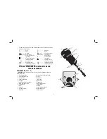
COMPONENTS (FIG. 1, 2)
WARNING:
Never modify the power tool or any part of it. Damage or personal
injury could result.
A. Quick release tabs
B. Depth adjustment ring
C. On/off switch
D. Spindle lock button
E. LED light
F. Guide pin groove (not shown)
G. Micro adjustment scale
H. Locking lever
I.
Base
J. Subbase
K. Sub-base screws
L. Guide pins
M. Locking lever adjustment screw
N. Collet
O. Collet nut
P.
Motor
unit
Q. Guide slot
R. Edge guide
S. Roller bearing guide
T.
Guide
screw
U. Spindle
V. Dust extraction adaptor
W. Dust exhaust port
X. Finger screws
FIG. 1
D
C
B
G
T
E
P
O
K
K
Q
J
O
N
Содержание DWE6005-XE
Страница 1: ...DWE6005 XE LAMINATE TRIMMER INSTRUCTION MANUAL ...
Страница 2: ......
Страница 13: ...11 ...
Страница 14: ......
Страница 15: ......

