English
5
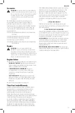
or AC ...........alternating current
or AC/DC .... alternating or
direct current
...................... Class II
Construction
(double insulated)
no .......................no load speed
n .........................rated speed
......................earthing terminal
.....................safety alert symbol
.....................visible radiation
..................... wear respiratory
protection
..................... wear eye
protection
..................... wear hearing
protection
..................... read all
documentation
SAVE THESE INSTRUCTIONS FOR
FUTURE USE
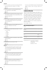
SPECIFICATIONS
Tool body
Machined steel, covered with plastic and glass
fiber housing.
Fasteners length
Must use direct fasteners 1/2" (13 mm) to 2-7/8"
(72 mm) total length.
Tool length
18-1/2" (47 cm)
Load type
Short .27 caliber (6.8/11) in a 10 load safety strip.
Power level
Brown (2), Green (3), Yellow (4), Red (5)
Fasteners type
.300" head direct drive fasteners
8 mm head direct drive fasteners
1/4"-20 threaded studs
Weight (without
pin/loads)
Tool with single shot nose piece.
7.1 lbs (3.23 kg)
Tool with magazine nose piece.
7.6 lbs (3.45 kg)
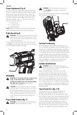
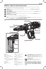
COMPONENTS (FIG. A)
WARNING:
Never modify the powder‑actuated
tool or any part of it. Damage or personal injury
could result.
Refer to Figure A at the beginning of this manual for a
complete list of components.
Intended Use
Your DFD270 powder‑actuated fastening tool is a power
adjustable, low velocity, fully‑automatic .27 caliber tool
which can be used to install .300" head drive fasteners,
8 mm head drive fasteners and 1/4"‑20 threaded studs, up
to 2‑7/8" (72 mm) in total length.
The DFD270 is designed for high speed and repetitive
volume fastening applications in concrete, certain masonry
materials, and A 36 steel. It includes a power adjustment
dial, allowing the operator to effectively decrease the power
level of the load being used.
DO nOT
use under wet conditions or in presence of
flammable liquids or gases.
Your powder‑actuated fastening tool has been designed for
professional use.
DO nOT
let children come into contact with the tool.
Supervision is required when inexperienced operators use
this tool.
ASSEMBLY AND ADJUSTMENTS
WARNING:
To reduce the risk of serious personal
injury, remove loads and fasteners before
making any adjustments or removing/installing
attachments or accessories.
An accidental
actuation can cause injury.
Attaching a Single Shot Nose or Magazine
to the Tool (Fig. B, C)
WARNING:
When replacing the single shot nose
or magazine, ALWAYS make sure the bumper is
properly installed.
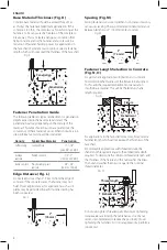
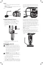
1. Make sure there are no fasteners or powder loads in
the tool.
2. With the tool facing away from the operator and
any bystanders, remove the single shot nose
6
or
magazine
9
by pressing the single shot nose release
button
7
or magazine release button
10
and
unscrewing it.
Fig. B
6
7
10
Fig. C
9
3. Before switching to the single shot nose or
magazine, remove the piston and check for wear.
Refer to
Replacing the Piston
and Bumper
under
Maintenence
.
4. Insert the piston into the tool. Be sure to push
it all the way back into the tool. Ensure piston is
positioned correctly.
5. Screw the single shot nose or magazine onto the tool
until the single shot nose release button
7
or magazine
release button
10
engages.
CAUTION:
If the release button does not engage,
take the tool to a
D
e
WALT
authorized service center
for repairs.
Содержание DFD270
Страница 55: ......


