21.4.15
Instruction manual UNIGATE
®
IC - Powerlink V. 2.3
43
Deutschmann Automation GmbH & Co. KG
Appendix
Slot X 1 (ZIF-socket)
PIN 1 of the IC is located up at the lever of the ZIF-socket.
Never place the IC into the socket back to front!
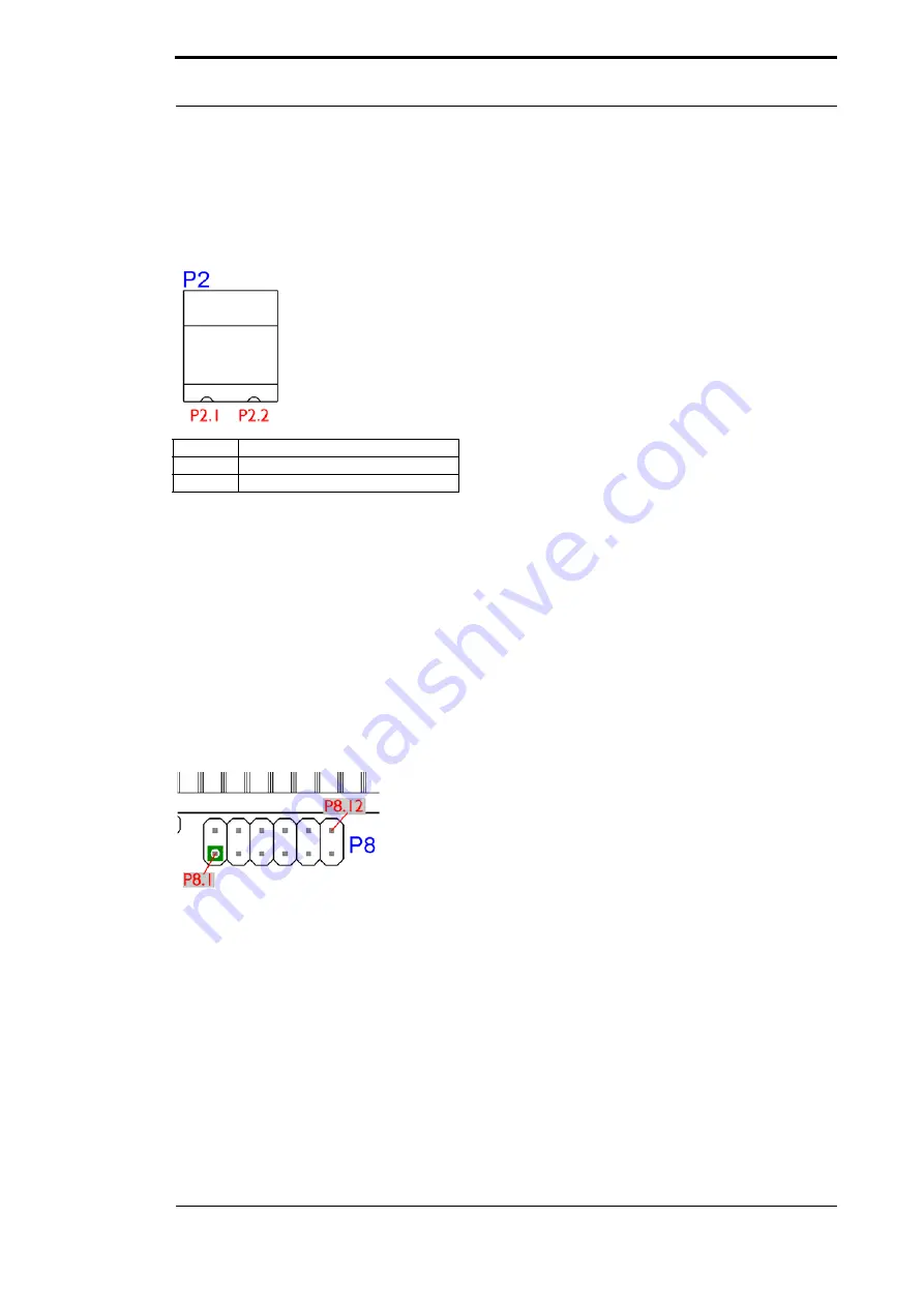
P 2
Pin
Signal
Pin 1
24 V DC
Pin 2
Ground
The basis board is supplied with voltage through this plug connector.
P 3 (AMP)
Powerlink plug connector, for the assignment of the connector see chapter 16.2.2.2.
P 4
Earth terminal 6.3 mm for basis board.
P 7
This plug is the basis board’s serial connection to the customer’s device and the connection to
the PC (Debug-interface).
For the pin assignment see chapter 16.2.2.1.
P 8
The illustration shows the arrangement of the pins. On this connector strip the signals of the
serial connection between IC and RS-drivers are wired. For an initial development you will prob-
ably also use an existing driver in your application. In order to exchange it later on, you can also
directly take the signals of the serial interface here.
Содержание UNIGATE IC - Powerlink
Страница 2: ......
Страница 6: ...Deutschmann Automation GmbH Co KG 6 Instruction manual UNIGATE IC Powerlink V 2 3 21 4 15 ...
Страница 8: ...Deutschmann Automation GmbH Co KG 8 Instruction manual UNIGATE IC Powerlink V 2 3 21 4 15 ...
Страница 50: ......


