28.9.20
Fieldbus-Gateway UNIGATE
®
CX C4Map - PROFIBUS V. 1.0
41
Deutschmann Automation GmbH & Co. KG
Communication interface PROFIBUS DP
14 Communication interface PROFIBUS DP
14.1 Bus line with copper cable
This interface is located on the module in the form of a 9-pin D-SUB socket on the front side of
the housing.
•
Plug the PROFIBUS connector onto the SUB-D socket labelled "PROFIBUS DP".
•
Firmly screw the securing screws of the plug connector tight using a screwdriver.
•
If the module is located at the start or end of the PROFIBUS line, you must connect the bus ter-
minating resistor integrated in the gateway. In order to do this, slide the slide switch to the posi-
tion labelled ...on...
•
If the module is not located at the start or at the end, you must set the slide switch to position
"off".
14.2 Line routing, shield and measures to combat interference voltage
This chapter deals with line routing in the case of bus, signal and power supply lines, with the aim
of ensuring an EMC-compliant design of your system.
14.2.1 General information on line routing
Inside and outside of cabinets
In order to achieve EMC-compliant routing of the lines, it is advisable to split the lines into the fol-
lowing line groups and to lay these groups separately.
Group A:
• shielded bus and data lines (e. g. for PROFIBUS DP, RS232C and printers etc.)
• shielded analogue lines
• unshielded lines for DC voltages
60 V
• unshielded lines for AC voltage
25 V
• coaxial lines for monitors
Group B:
• unshielded lines for DC voltages
60 V and
400 V
• unshielded lines for AC voltage
24 V and
400 V
Group C:
• unshielded lines for DC voltages > 400 V
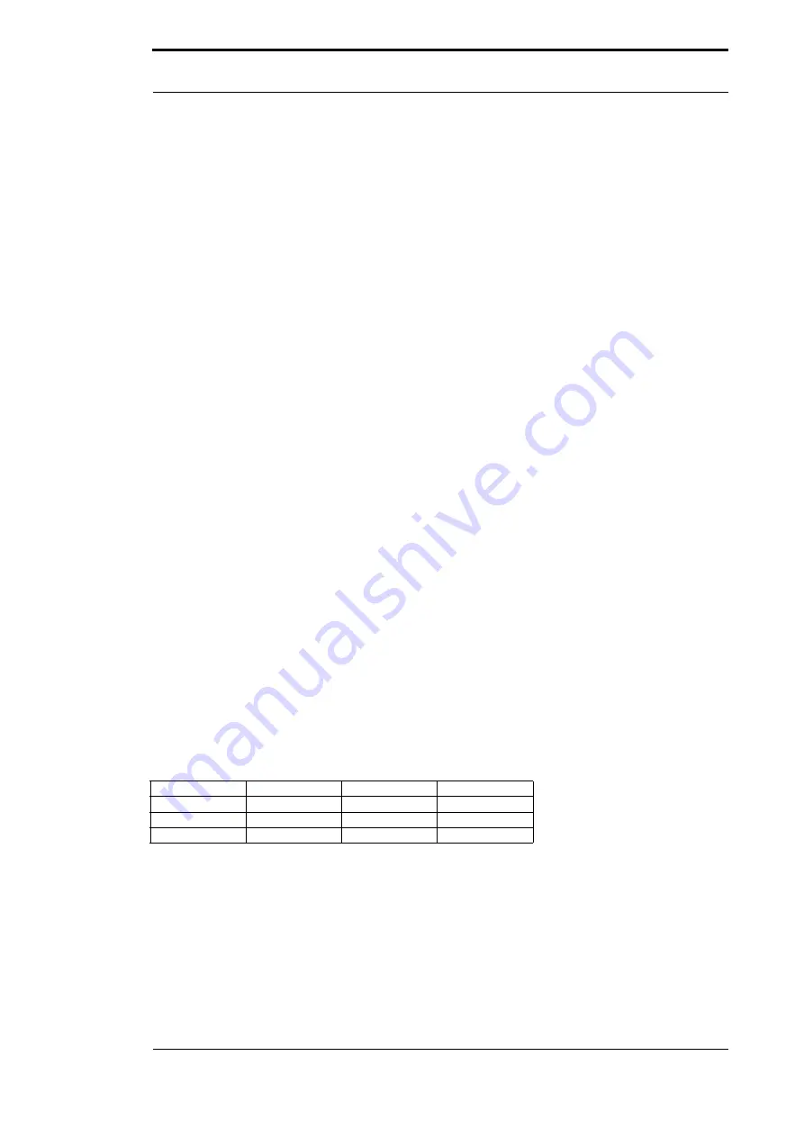
The table below allows you to read off the conditions for laying the line groups on the basis of the
combination of the individual groups.
Group A
Group B
Group C
Group A
1
2
3
Group B
2
1
3
Group C
3
3
1
Table 3: Line laying instructions as a function of the combination of line groups
1) Lines may be laid in common bunches or cable ducts.
2) Lines must be laid in separate bunches or cable ducts (without minimum clearance).
3) Lines must be laid in separate bunches or cable ducts inside cabinets but on separate cable
racks with at least 10 cm clearance outside of cabinets but inside buildings.
Содержание UNIGATE CX C4Map
Страница 2: ...Handbuch Art Nr V4412E ...
Страница 56: ......


