Declaration of conformity
Deutschmann Automation GmbH & Co. KG
40
UNIGATE Fieldbus Gateway UNIGATE CL - Powerlink V. 1.8
17.6.10
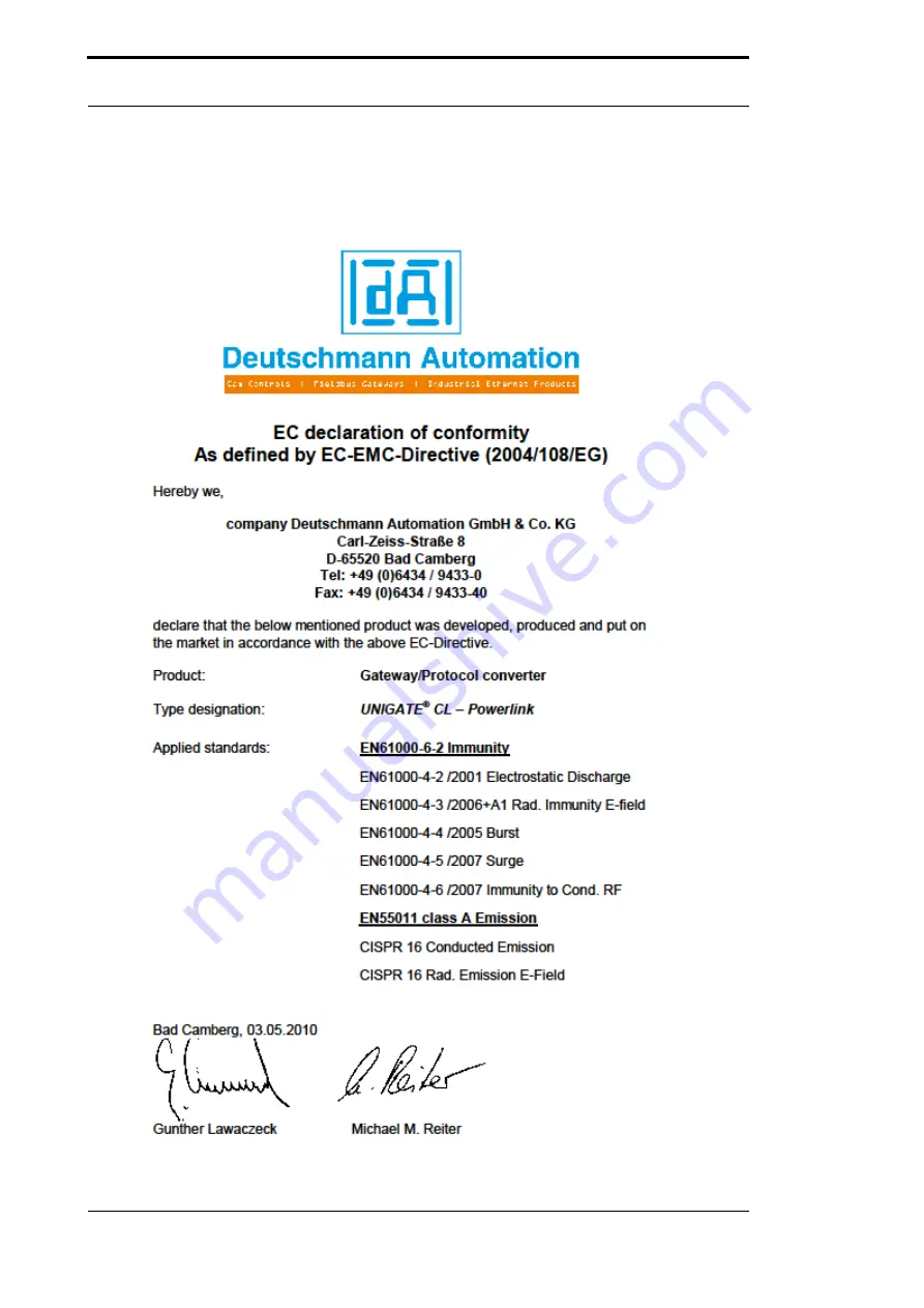
19 Declaration of conformity
19.1 EC declaration of conformity
Страница 1: ...al Fieldbus Gateway UNIGATE UNIGATE CL Powerlink V3653E Deutschmann Automation GmbH Co KG Carl Zeiss Str 8 D 65520 Bad Camberg Tel 49 0 6434 9433 0 Hotline 49 0 6434 9433 33 Fax 49 0 6434 9433 40 Internet http www deutschmann de ...
Страница 2: ......
Страница 3: ...fer sizes at the UNIGATE CL 14 5 3 Framing Check 14 6 SSI interface 15 6 1 Initiation of the SSI interface 15 6 2 Hardware wiring 15 7 The Debug interface 17 7 1 Overview of the Debug interface 17 7 2 Starting in the Debug mode 17 7 3 Communication parameter for the Debug interface 17 7 4 Possibilities with the Debug interface 17 7 5 Commands of the Debug interface 17 8 Mode of operation of the sy...
Страница 4: ...ace 29 12 4 3 Rotary coding switch High and Low Powerlink Node ID 29 12 5 The Debug cable for UNIGATE SC 29 13 Error handling 30 13 1 Error handling at UNIGATE CL 30 14 Installation guidelines 31 14 1 Installation of the module 31 14 1 1 Mounting 31 14 1 2 Removal 31 14 2 Wiring 31 14 2 1 Connection systems 31 14 2 1 1 Power supply 31 14 2 1 2 Equipotential bonding connection 31 14 2 2 Ethernet Po...
Страница 5: ...n GmbH Co KG 16 8 Shield connection 37 16 9 Connecting the supply voltage 37 16 10 Project planning 37 17 Servicing 38 17 1 Returning a device 38 17 2 Downloading PC software 38 18 Annex 39 18 1 Hexadecimal table 39 19 Declaration of conformity 40 19 1 EC declaration of conformity 40 ...
Страница 6: ...Deutschmann Automation GmbH Co KG 6 UNIGATE fieldbus gateway UNIGATE CL Powerlink V 1 8 17 6 10 ...
Страница 7: ... publication is however reviewed regularly Necessary amendments are incorporated in the following editions We would be pleased to receive any improvement proposals which you may have Copyright Copyright C Deutschmann Automation GmbH Co KG 1997 2010 All rights reserved This document may not be passed on nor duplicated nor may its contents be used or disclosed unless expressly permitted Violations o...
Страница 8: ...irements if you 1 comply with the installation guidelines described in the User Manual when installing and oper ating the module 2 also follow the rules below on installation of the equipment and on working on switch cabinets 1 4 Installation of the unit Modules must be installed in electrical equipment rooms areas or in enclosed housings e g switch boxes made of metal or plastic Moreover you must...
Страница 9: ...tive Consequently the module does not have a Declaration of Conformity in relation to the EU Machinery Directive 2 2 EU Machinery Directive The EU Machinery Directive stipulates the requirements applicable to a machine The term machine is taken to mean a totality of connected parts or fixtures see also EN 292 1 Para graph 3 1 The module is a part of the electrical equipment of the machine and must...
Страница 10: ...to Powerlink CN Controller Nodes The terminal unit s protocol is converted in the UNIGATE via a Script The module CL Powerlink essentially consists of the following hardware components Electrically isolated Powerlink interface 32 bit processor Hynet32s RAM and FLASH Optionally electrically isolated on the RS side Serial interface RS232 RS485 and RS422 to the device connected externally ...
Страница 11: ...17 6 10 UNIGATE Fieldbus Gateway UNIGATE CL Powerlink V 1 8 11 Deutschmann Automation GmbH Co KG Introduction 3 1 UNIGATE CL software flow chart ...
Страница 12: ...Introduction Deutschmann Automation GmbH Co KG 12 UNIGATE Fieldbus Gateway UNIGATE CL Powerlink V 1 8 17 6 10 3 2 UNIGATE application diagram The following graph shows a typical connection scheme ...
Страница 13: ...into consideration for the setting of the test mode Now the Gateway has to be restarted with these settings by a short disconnection from the power supply In the test mode the Gateway always operates with the settings 9600 baud no parity 8 databits and 1 stopbit The test mode may be helpful to integrate the Gateway in the relevant environment for instance to test the parameters of the RS interface...
Страница 14: ...at is capable for Script For it please check in the Protocol Developer under Device Control Hardware 5 3 Framing Check The length of the stop bit received by the Gateway is checked through the function Framing Check Here the stop bit generated by the Gateway is always long enough so that connected participants can evaluate the stop bit Please be aware that the function Framing Check becomes effect...
Страница 15: ... 0 Reserved 1 Output value without change i e binary encoder 2 Output value changed from Gray to Binary i e Gray encoder 2 Reserved moveconst wTyp 2 i e 12 Bit Gray Load the Script into the device Open WINGATE and activate the device in the configuation mode see chapter 4 1 Configuration mode config mode an actuation message appears that looks in line with the following example CL PB Special Firmw...
Страница 16: ...bH Co KG 16 UNIGATE Fieldbus Gateway UNIGATE CL Powerlink V 1 8 17 6 10 X1 3pin 4pin screw plug connector Pin no Name Function at SSI 1 Rx 232 n c 2 Tx 232 n c 3 AP GND n c 4 Rx 422 SSI DAT 5 Rx 422 SSI DAT 6 Tx 422 SSI CLK 7 Tx 422 SSI CLK ...
Страница 17: ...perating with 9600 baud no parity 8 data bit 1 stop bit It is not possible to change this parameter in the Protocol Developer Please consider the fact that these settings have to be in accordance with those of the PC COM interface and that the flow control protocol has to be set on none there 7 4 Possibilities with the Debug interface Usually the Protocol Developer is connected to the Debug interf...
Страница 18: ...e var a_ObjectTableBuffer buffer 32 2 Objekte 16 32 Anzahl Obj 16 reservierter Speicherbereich InitObjectTable 2 a_ObjectTableBuffer 0 erzeugen der Variablen für die einzelnen Obj var a_Variable_2000 buffer 6 var a_Variable_2001 buffer 6 erzeugen eines Obj CreateObject index object_type subindex data_type flags MPtr_Buffer CreateObject 0x2001 0x7 0 0x6 0x08 a_Variable_2001 0 CreateObject 0x2000 0x...
Страница 19: ...rt es kann jederzeit von anderen Teilnehmern ausgelesen werden Gleichzeitig wird jedes Obj in eine Queue geschrieben und zwischengespeichert Diese Queue kann mit folgendem Kommando ausgelesen werden sind keine neuen SDO s eingegangen liefert das Kommando den Returncode 0x03 zurück Die Queue kann 255 SDO s empfangen wobei die jeweilige Datengröße auf 255 Byte begrenzt ist ReadNewEPLObjectData w_Ind...
Страница 20: ...FFFh and the device profile number referenced by object 1000h is the device profile of the first device in the Object Dictionary All other devices of a multiple device module identify their profiles at objects Manufact Dev Name Obj 0x1008 var variable buffer 15 moveconst variable 0 UNIGATE Ethernet Powerlink CL 0x00 Max Len 32 SetByVar DeviceName variable 0 default CL RS EP CL default IC IC EP SC ...
Страница 21: ...nsferable data 8 5 Startup phase The Master sets up a TCP IP or a UDP IP connection to the Gateway during the startup phase Only after a correct termination of the startup phase the data exchange with external devices will take place Message Amount of messages Message length Rx PDO 1 Maximum 1514 bytes Tx PDO 1 Maximum 1514 bytes SDO Maximum 256 pcs Maximum variable length per SDO 256 bytes ...
Страница 22: ...group of commands deals with the communication in general This group s commands enable the Gate way to send and receive data on the serial side as well as on the bus side 9 4 Independence of buses Basically the Scripts do not depend on the bus they are supposed to operate on It means that a Script which was developed on a Profibus Gateway can also be operated on an Interbus without changes since t...
Страница 23: ...rovided that it is not the first start Typical for Windows Script commands can be added by means of the mouse or the keyboard As far as defined and required for the corresponding command the dialog to the corresponding command is displayed and after entering the values the right text is automatically added to the Script The insertion of new commands by the Protocol Developer is carried out in a wa...
Страница 24: ...cript sys The remaining files belong to the WEB Server Further information can be found in the corresponding chapter WEB Server 10 1 Script update via FTP The dcs file generated by the Protocol Developer has to be stored as script dcs by the FTP on the Gateway subdirectory flash When the Gateway starts up it identifies converts and inte grates this file into the file script sys where the Script is...
Страница 25: ... places the corresponding String at the variable s place The other way round Strings that are passed on via POST by the HTML page with the corresponding variable name are copied in to the corresponding Script buffer The Syntax looks as follows exec cmd_argument xxxxx For xxxxx the following expressions are possible DisplayFWVersion DisplayBLVersion DisplaySerial DisplayMacID DisplayStationName Dis...
Страница 26: ...to the external device RS interface The serial interface is available at the plug accessible on the upper side of the device Pin assignment X1 3 pole and 4 pole screw type plug connector For the operation at a 485 interface the two pins labeled 485 have to be connected together Also the two pins 485 Pin No Name Function 1 Rx 232 Receive signal 2 Tx 232 Transmit signal 3 AP GND Application Ground 4...
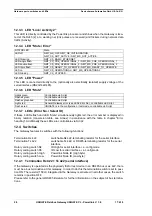
Страница 27: ...AC voltage 12 3 LEDs The Gateway UNIGATE CL Powerlink features 10 LEDs with the following significance 12 3 1 LED Pwr This LED is connected directly to the Powerlink supply voltage 12 3 2 LED Link Activity 1 This LED is directly controlled by the Powerlink processor and shines when the Gateway is loca ted at the RJ45 1 at a working net link pulses are received and flickers during network data traf...
Страница 28: ...e configmode Rotary coding switch S5 ID Low for serial interface i e configmode Rotary coding switch High Powerlink Node ID High byte Rotary coding switch Low Powerlink Node ID Low byte 12 4 1 Termination Rx 422 Tx 422 serial interface If the Gateway is operated as the physically first or last device in an RS485 bus or as 422 there must be a bus termination at this Gateway In order to do this the ...
Страница 29: ...tched on or always after a Script command has been executed The switch positions EE testmode and FF config mode are reserved 12 4 3 Rotary coding switch High and Low Powerlink Node ID The last byte of the Powerlink IP address is set hexadecimal with these two switches This value is read in only once when the Gateway is activated The value can also be read out or analyzed through the Script command...
Страница 30: ...ion purposes and are then automatically reset If such warnings occur frequently please inform After Sales Service In the configuration mode these displays are not valid and only meant for internal use Table 1 Error handling at UNIGATE CL For user defined errors the flash frequency is 0 5 hertz The error is displayed as long as defined by Set Warning Time LED8 LED4 LED2 LED1 Error no resp ID Error ...
Страница 31: ...The standard mounting channel may also be mounted vertically so that the module is mounted turned through 90 14 2 Wiring 14 2 1 Connection systems The following connection systems must resp may be used when wiring the module Standard screw type plug connection power supply RS 8 pin RJ45 plug in connection Powerlink connection a In the case of standard screw type terminals one lead can be clamped p...
Страница 32: ...ages 60 V unshielded lines for AC voltage 25 V coaxial lines for monitors Group B unshielded lines for DC voltages 60 V and 400 V unshielded lines for AC voltage 24 V and 400 V Group C unshielded lines for DC voltages 400 V The table below allows you to read off the conditions for laying the line groups on the basis of the combination of the individual groups Table 3 Line laying instructions as a ...
Страница 33: ...quencies Connecting the shield at one end may be more favorable if it is not possible to lay an equipotential bonding line analogue signals a few mV resp mA are to be transmitted foil shields static shields are used In the case of data lines for serial couplings always use metallic or metallized plugs and connec tors Attach the shield of the data line to the plug or connector housing If there are ...
Страница 34: ...W x H x D 6 Installation position Any 7 Weight Approx 130 g 8 Operating temperature 0ºC 55ºC 9 Storage transport temperature 40 ºC 70 ºC 10 Atmospheric pressure during operation during transport 795 hPa 1080 hPa 660 hPa 1080 hPa 11 Installation altitude 2000 m 4000 m Unrestricted Restricted Ambient temperature 40ºC 12 Relative humidity Max 80 No condensation no corrosive atmosphere 14 External pow...
Страница 35: ...l duplex at RS422 Difference signal 3 Transmission method Multimaster CSMA CD Master slave Master slave 4 Number of users Transmitters Receivers 512 512 1 1 32 32 5 Cable length Maximum Depending on baudrate 100 m 15 m no 1200 m 93 75 kBd 1200 m 312 kBd 500 m 625 kBd 250 m 6 Bus topology Star line Point to point Line 7 Data rate Maximum Standard 100 Mbit s 100 Mbit s 120 kBit s 2 4 k B 4 8 k B 9 6...
Страница 36: ... V DC power supply DIN 19240 Type file or EDS file and user manual a sample EDS file as well as the user manual can be ordered separately or downloaded free of charge from our homepage at www deutschmann de 16 3 Installation The UNIGATE CL PL module features protection type IP20 and is thus suitable for switch cabinet use The device is designed for snapping onto a 35 mm DIN rail 16 4 Dimensional d...
Страница 37: ...oning the process device 16 8 Shield connection Earth the top hat rail onto which the module has been snapped 16 9 Connecting the supply voltage Please connect 10 33 DC voltage to the terminals provided for this 16 10 Project planning Use any project planning tool for project planning If the required EDS file was not supplied with your project planning tool a sample file can be found on the Intern...
Страница 38: ... department 49 0 6434 9433 0 Technical hotline 49 0 6434 9433 33 Fax sales department 49 0 6434 9433 40 Fax technical hotline 49 0 6434 9433 44 E mail technical hotline hotline deutschmann de 17 1 Returning a device If you return a device we require as comprehensive a fault error description as possible We require the following information in particular What error number was displayed What is the ...
Страница 39: ...nk V 1 8 39 Deutschmann Automation GmbH Co KG Annex 18 Annex 18 1 Hexadecimal table Hex Decimal Binary 0 0 0000 1 1 0001 2 2 0010 3 3 0011 4 4 0100 5 5 0101 6 6 0110 7 7 0111 8 8 1000 9 9 1001 A 10 1010 B 11 1011 C 12 1100 D 13 1101 E 14 1110 F 15 1111 ...
Страница 40: ...Declaration of conformity Deutschmann Automation GmbH Co KG 40 UNIGATE Fieldbus Gateway UNIGATE CL Powerlink V 1 8 17 6 10 19 Declaration of conformity 19 1 EC declaration of conformity ...
Страница 41: ...17 6 10 UNIGATE Fieldbus Gateway UNIGATE CL Powerlink V 1 8 41 Deutschmann Automation GmbH Co KG Declaration of conformity ...
Страница 42: ...Declaration of conformity Deutschmann Automation GmbH Co KG 42 UNIGATE Fieldbus Gateway UNIGATE CL Powerlink V 1 8 17 6 10 ...