


Hardware ports, switches and LEDs
Deutschmann Automation GmbH & Co. KG
26
UNIGATE Fieldbus Gateway UNIGATE CL - Powerlink V. 1.8
17.6.10
12 Hardware ports, switches and LEDs
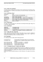
12.1 Device labeling
Picture 1: Terminal labeling and termination
Picture 2: Front panel: Rotary switches and LEDs
12.2 Connectors
12.2.1
Connector to the external device (RS-interface)
The serial interface is available at the plug accessible on the upper side of the device.
Pin assignment X1 (3-pole and 4-pole screw-type plug connector)
For the operation at a 485-interface the two pins labeled "485-" have to
be connected together.
Also the two pins "485+".
Pin No.
Name
Function
1
Rx 232
Receive signal
2
Tx 232
Transmit signal
3
AP-GND
Application Ground
4
Rx 422+ (485+)
Receive signal
5
Rx 422- (485-)
Receive signal
6
Tx 422+ (485+)
Transmit signal
7
Tx 422- (485-)
Transmit signal


