4
1.2)
INSTALLATION
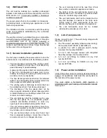
This unit must be installed by a qualified, professional
installer in accordance with these instructions and CSA
B139 section 4.3. If improperly installed, a hazardous
condition could result.
The power venter shall not be installed on incinerators,
incinerating toilets, condensing type appliances or solid
fuel burning appliances.
The installation shall be in accordance with the existing
codes and regulations established by the authorities
having jurisdiction.
The venting unit may be installed through a combustible
wall with a maximum thickness of 8 inches or through a
non-combustible wall of 16 inches including a
combustible exterior wall of no more than 8 inches. The
minimum wall thickness is 2 inches. A type B vent shall
not be used in the venting system.
1.2.1) General installation guidelines
The first step in installing the power venter is to find the
location that is in accordance with the following criteria:
The flue discharge terminal of the venting system
shall be installed not less than 7 feet above any
paved driveway or paved walkway;
A power venting system shall not terminate within
6 feet of a mechanical air supply inlet to any
building including soffit opening or within 6 feet of
a window, door or property line;
The flue discharge terminal shall not be installed
within 3 feet horizontally of the vertical center-line
above a gas meter/regulator assembly;
The venting system discharge terminal shall not
be installed less than 1 foot above grade level;
The discharge of the flue gases shall not be
above a paved sidewalk or paved driveway which
is located between two buildings where their use
is common to both buildings;
The vent terminal shall be installed such a way
that the flue gases do not jeopardize people,
overheat combustible structures or enter any
openings of surrounding building within 6 feet;
The vent terminal shall not be within 6 feet of any
gas service regulator vent outlet or within 3 feet of
any oil tank vent or oil tank fill inlet;
The vent terminal shall not be less than 6 feet
from an adjacent building or closer than 3 feet to
an inside corner of an L shaped structure;
The vent terminal shall not be less than 6 feet
from another combustion appliance air intake;
The bottom of the vent termination shall not be
installed less than 1 foot above any surface where
snow, ice or debris may accumulate;
The vent termination shall not be located such a
way that damage is caused to the brick work,
mortar, wood or other components of the con-
struction by flue gas condensate or temperature;
The vent termination shall not be located
underneath a veranda, porch or deck.
1.3)
List of components
Please consult Figure 1. The parts being shipped with
the power venter are:
a. The "Fan-motor" assembly (stainless steel casing).
Part number SWV-1M-2S or SWV-2M-2S;
b. A junction box with a pressure switch, factory
mounted. Part number R99F001;
c. A 3 to 6 inch flue-pipe reducer with integrated
back-flow damper. Part number FD-02;
d. A 6 to 5 inch fitting; for SMH-3 kit only. Part
number Z07F010;
e. A 6 to 8 inch fitting; for SMH-5 kit only. Part
number Z07F005.
1.4)
Power venter installation
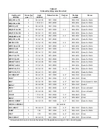
Verify if the power venter is correctly sized according to
Table 1. All appliances must enter the vent system on
the inlet side of the power venter.
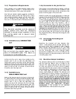
You must install a barometric draft regulator in
accordance with your heating unit instruction manual.
See Figure 1.
Содержание SMH-1-BR
Страница 2: ......
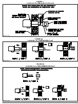
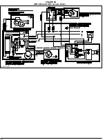
Страница 10: ...DNS 0225 Rev A DNS 0226 Rev A FIGURE 1 SMH system General arrangement FIGURE 2 Main system dimensions...
Страница 13: ...13 DNS 0231 Rev C DNS 0232 Rev C FIGURE 5C AMI and HE 1 speed Beckett FIGURE 5D AMI and HE 1 speed Riello...
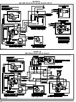
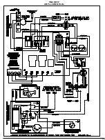
Страница 14: ...14 DNS 0407 Rev C FIGURE 5E AMT SM and OSR 2 speeds Riello...
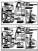
Страница 15: ...15 FIGURE 5F AMP and OMB Riello...
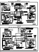
Страница 16: ...16 FIGURE 5G AMP and OMB Beckett DNS 0622 Rev A...


