background image

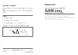
1

Commodity

Tray

Capacity Label

Level

Indicator

Zero Button

Weighbridge

Weight
Display

Locking
Nut

Mounting

Foot

INSTALLATION

On receipt of your AS-300 series scale, carefully unpack the scale removing all packing material.
Examine the scale to make certain that there is no shipping damage. Should damage be discovered
contact the shipping company as soon as possible. The packing material and shipping carton should
be retained for possible examination by the shipping company.

Determine where the scale is to be located. It should be a smooth surface capable of supporting both
the scale and any load apt to be placed on the scale. It should not be in direct sunlight nor should it
be subject to air flow from heating/cooling vents, fans or similar devices.

Place the scale in the chosen location and remove the stainless steel commodity tray. The tray can
be removed by lifting upward on it removing it from the weighbridge. Locate the small level indicator
on the weighbridge and check to make certain that the scale is level. If the level indicator does not
show a level indication, the mounting feet should be adjusted to obtain a level condition. To adjust a
mounting foot, first loosen the lock nut then turn the mounting foot in the required direction to raise or
lower that corner of the scale. Once a level condition has been achieved, secure the mounting foot
settings by tightening each of the lock nuts. Replace the commodity tray on the weighbridge. Refer to
Figure No. 1 for additional information.

Make certain that the power switch on the rear of the scale is in the OFF position then plug the power
cord into a 115 vac grounded polarized power outlet and make certain that the power cord is not in
the way of normal traffic. The socket-outlet shall be installed near the equipment and shall be easily
accessible. If you are unsure whether your power outlet is correct, you should consult a qualified
electrician. Turn the power switch to the ON position.

If the display illuminates with a display segment test, installation of the scale is complete. If not, check
to make sure that the power outlet and the scale fuse are good.

SCALE INSTALLATION

Figure No. 1

Содержание AS-300D Series

Страница 1: ...AS 300D Series Smart Bench Scales Owner s Manual T DET C O E A Division of Cardinal Scale Manufacturing Co PO BOX 151 WEBB CITY MO 64870 417 673 4631 8527 M214 O1 Rev B 01 03 Printed in USA ...

Страница 2: ... editorial or pictorial content in any manner is prohibited No patent liability is assumed with respect to the use of the information contained herein While every precaution has been taken in the preparation of this book we assume no responsibility for errors or omissions Neither is any liability assumed for damages resulting from the use of the information contained herein All instructions and di...

Страница 3: ... check to make certain that the scale is level If the level indicator does not show a level indication the mounting feet should be adjusted to obtain a level condition To adjust a mounting foot first loosen the lock nut then turn the mounting foot in the required direction to raise or lower that corner of the scale Once a level condition has been achieved secure the mounting foot settings by tight...

Страница 4: ...ed to the scale Pounds Only Mode Selected Optional AS 350D only W Standard Resolution Request to Transmit Scale Weight This command can only be used when the scale mode has been set to the Pounds Only Mode Scale Output Format STX Snnn nn CR where STX ASCII STX nnn nn scale weight in pounds with decimal point CR Carriage Return If the scale weight is below zero over capacity in motion or at center ...

Страница 5: ...OT 04 Version Request Command Causes the scale to transmit scale software revision level in the following format STX VVVCC ETX where STX ASCII STX VVV 3 Digit Revision Level CC Checksum Digits ETX ASCII ETX The checksum digits CC are formed by exclusive or ing all three version number digits VVV to produce a checksum byte This byte is then split into two nibbles with the high nibble transmitted fi...

Страница 6: ... 8527 C099 1A Serial Cable 25 1 8527 B205 08 Load Cell Spacer 26 1 8527 D201 08 Base Assembly 27 1 8527 D210 08 Top Cover 28 1 8527 C211 08 Display Overlay 29 1 6670 0003 RFI Filter Assy 30 1 6610 4046 Fuse Holder 31 1 6610 4019 1 4 AMP Slow Blow Fuse 32 1 8527 B122 0A AC Cable Assembly 33 1 6980 0008 Strain Relief Bshng 34 4 6021 0448 4 40 X 75 Flat Head Screw 35 2 8527 B109 0A Cable Assembly 36 ...

Страница 7: ...5 15 14 17 16 18 31 30 37 38 43 29 32 9 10 35 6 1 25 36 19 39 34 28 21 26 23 5 9 8 40 17 16 20 50 49 2 27 18 3 48 22 24 PART IDENTIFICATION Figure No 2 ...

Страница 8: ...U N A M E D S I G U N E D F A C T R E D I N U S A U N A M E D S I G U N E D F A C T R E D I N U S A ...

Отзывы: