


LBB Series Oven Owner
’s Manual
P
REFACE
Version 20
Figures
Figure 1. Disconnect Switch.......................................................................................................... 19
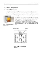
Figure 2. LBB Forced Convection Benchtop Oven. ..................................................................... 20
Figure 3. Uniflow Airflow through the LBB Oven. ...................................................................... 20
Figure 4. LBB Series Oven Primary Control Instrument .............................................................. 21
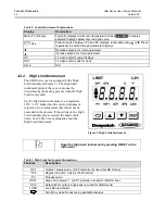
Figure 5. High Limit Instrument. .................................................................................................. 22
Figure 6. Protocol 3 Operator Interface. ........................................................................................ 23
Figure 7. LBB Series Oven Name Plate Example. ........................................................................ 26
Figure 8. LBB Series Oven with Top Removed. ........................................................................... 26
Figure 9. Wiring Access through Rear of Oven. ........................................................................... 27
Figure 10. Close-up of Connector Block. ...................................................................................... 27
Figure 11. LBB Series Oven Control Panel. ................................................................................. 31
Figure 12. Adjust Damper to Set Exhaust Vent by rotating the outer component. ....................... 31
Figure 13. Remove Control Panel to Access Control Instrument (using T20 Torx bit driver). .... 45
Figure 14. Providing easy access to the Control instrument. ........................................................ 46
Figure 15. Remove old Control and High Limit Instruments and Wiring (Rear View). ............... 46
Figure 16. Prepare to remove control instrument by removing the mounting bracket. ................. 47
Figure 17. Connections to Control Instrument. ............................................................................. 47
Figure 18. High Limit Connector Block on Control Board. .......................................................... 48
Figure 19. Press and Hold Tabs to Remove High Limit Instrument. ............................................ 49
Figure 20. Connections to High Limit Instrument. ....................................................................... 49
Figure 21. Remove Screws to Remove Each Duct (using T15 Torx bit driver. ............................ 50
Figure 22. Heater element connections. ........................................................................................ 51
Figure 23. Typical Heating Element (Inset connections see Figure 22) . ...................................... 52
Figure 24. Fan Motor Location. .................................................................................................... 53
Figure 25. Separate fan wheel from fan motor shaft. .................................................................... 54
Figure 26. Optional LBB Oven Stand. .......................................................................................... 60
Figure 27. Timer Option Displays and Switches. .......................................................................... 61
Tables
Table 1. Operating/Environmental Conditions (For indoor use). .................................................. 14
Table 2. Control Instrument Explanations. .................................................................................... 22
Table 3. High Limit Instrument Explanations. .............................................................................. 22
Table 4. Control Instrument Set-up Parameters. ........................................................................... 33
Table 5. Control Instrument Configuration Parameters. ............................................................... 34
Table 6. High Limit instrument Setup Parameters. ....................................................................... 38
Table 7. Common Technical Issues and Remedies. ...................................................................... 55
Содержание LBB 1-23
Страница 3: ...LBB Series Oven Owner s Manual PREFACE Version 20...
Страница 4: ...PREFACE LBB Series Oven Owner s Manual 4 Version 20...
Страница 62: ...APPENDICES LAC LFC Series Oven Owner s Manual 62 Version 20 8 3 3 Operating the Timer...
Страница 63: ...LAC LFC Series Oven Owner s Manual APPENDICES Version 20 63...


