7 / 43
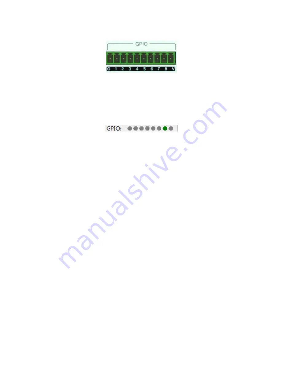
2.3 GPIO
G: Ground
1~8: Port 2-8 are freely configurable input or output, port 1 only input function.
V: The default GPIO power output pin(5V).
GPIO state of software:
Note:
●
Output high;
●
Input high;
●
Output low;
●
Input low ● Disable
Port output: each output port is OC output, the default reference voltage 5V and the reference voltage can
also be
external is less than 15V, take the default reference voltage, the total output ports is 200mA:
Input port: lowest level of input high > 2V, highest level of input high <VCC+0.7V; highest level of input
low <0.3V.
Use of GPIO:
the output: is a parameter matrix of internal changes (such as mute), cause the change of the
output level of a
GPIO output pins, to drive an external circuit.
Audio matrix internal change -> GPIO pin level change ->external driving circuit.
input: GPIO is an input pin level due to changes in the external circuit is changed, thus a
parameter matrix trigger changes.
The external circuit state changes -> GPIO pin level change -> audio matrix internal change.
The operation details see Appendix 2.
3. Software Operation
3.1
Web Control and Software Download
Device default IP address ex factory is 192.168.1.200, please add IP address fallen into the same network
segment as the device.
After the device started, input address, in webpage http://192.168.1.200/:
Содержание DMD2 Series
Страница 1: ...DIGITALAUDIO PROCESSOR USE MANUAL ...
Страница 23: ...22 43 6 GPIO Setting Please refer to the appendix ...


