background image

44/48

B EN XS00 DFU WEB  /  Rev.08  /  01-2018 (Old ZF 190270.EN)

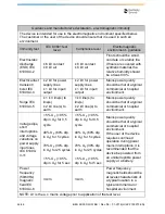
Guidance and manufacturer's declaration - electromagnetic immunity

The device is intended for use in the electromagnetic environment specified below. 
The customer or the user of the device should ensure that it is used in such an 
environment.

Immunity test

IEC 60601 test 

level

Compliance level

Electromagnetic 

environment - guidance

Electrostatic 
discharge 
(ESD) IEC 
61000-4-2

± 6 kV contact
± 8 kV air

± 6 kV contact
± 8 kV air

Floors should be wood, 
concrete or ceramic tile.
If floors are covered with 
synthetic material, the 
relative humidity should 
be at least 30%.

Electrical fast 
transient/
burst IEC 
61000-4-4

± 2 kV for power 
supply lines
± 1 kV for input/
output

± 2 kV for power 
supply lines
± 1 kV for input/
output

Mains power quality 
should be that of a typical 
commercial or hospital 
environment.

Surge IEC 
61000-4-5

± 1  kV line(s) to 
line(s)
± 2 kV line(s) to 
earth

1 kV line(s) to 
line(s)
± 2 kV line(s) to 
earth

Mains power quality 
should be that of a typical 
commercial or hospital 
environment.

Voltage dips, 
short 
interruptions 
and voltage 
variations on 
power supply 
input lines 
IEC 61000-
4-11

< 5% U

T

 (> 95% 

dip in U

T

) for 0,5 

cycle

40% U

T

 (60% dip 

in U

T

) for 5 cycles

70% U

T

 (30% dip 

in U

T

) for 25 cycles

< 5% U

T

 (> 95% 

dip in U

T

) for 5 sec

< 5% U

T

 (> 95% 

dip in U

T

) for 0,5 

cycle

40% U

T

 (60% dip 

in U

T

) for 5 cycles

70% U

T

 (30% dip 

in U

T

) for 25 cycles

< 5% U

T

 (> 95% 

dip in U

T

) for 5 sec

Mains power quality 
should be that of a typical 
commercial or hospital 
environment.
If the user of the device 
requires continued 
operation during power 
mains interruptions, it is 
recommended that the 
device be powered from 
an uninterruptible power 
supply or a battery.

Power 
frequency 
(50/60Hz) 
magnetic 
field IEC 
61000-4-8

3 A/m

3 A/m

Power frequency 
magnetic fields should be 
at levels characteristic of 
a typical location in a 
typical commercial or 
hospital environment.

NOTE: U

T

 is the a.c. mains voltage prior to application of the test level.

Содержание X-Smart

Страница 1: ...EN User Manual ...

Страница 2: ...2 48 B EN XS00 DFU WEB Rev 08 01 2018 Old ZF 190270 EN PAGE INTENTIONALLY LEFT BLANK ...

Страница 3: ... Equipment 10 2 Contents 11 3 Product Main Specifications 11 4 Product Description 12 4 1 Operation Panel and LCD Panel 13 4 2 Power 13 4 3 Speed 13 4 4 Torque 14 4 5 Program 14 4 6 Reverse 14 4 7 Gear Ratio 15 4 8 Auto Reverse 15 4 9 Memo 16 4 10 CHARGE Lamp Orange 16 4 11 AC IN Lamp Green 16 4 12 Bar Display 17 5 How to connect each part 17 5 1 Connecting Motor Handpiece 17 5 2 Connecting AC Ada...

Страница 4: ...everse Function 23 6 6 Completion of Medical Treatment 25 7 Additional Directions For Use 26 7 1 Program 26 7 2 Initialization of Program Factory set configuration 27 7 3 Battery Refresh 27 7 4 Calibration 29 7 5 Alarm Sound Volume Control 30 8 Cleaning 31 8 1 Lubricating Contra Angle 31 8 2 Cleaning Motor Handpiece 31 8 3 Cleaning Control Unit 31 8 4 Cleaning AC Adapter 31 9 Sterilization 32 9 1 ...

Страница 5: ...B EN XS00 DFU WEB Rev 08 01 2018 Old ZF 190270 EN 5 48 Table of contents 11 Error Code 35 12 Troubleshooting 37 13 Warranty 40 14 Disposing Product 40 15 Identification of Symbols 41 ...

Страница 6: ...rt pacemaker or other electrical equipment and has been cautioned against the use of small electrical appliances such as electric shavers hair dryers etc it is recommended to not use the X Smart This motor should not be used for severe curved root canal preparation Do not use X Smart for implant or any other dentist procedure outside endodontics 1 3 Warnings Use the specified batteries for this pr...

Страница 7: ...e resistance When installing the device leave approximately 10cm around the control unit for easy access to the inlet and the power cord Portable and mobile radio frequency RF communications equipment can affect the proper functioning of X Smart The X Smart requires special precautions as regards electromagnetic compatibility EMC and must be installed and commissioned in strict conformity with the...

Страница 8: ...ed deformed or non ISO conforming file Using such a file may result in personal injury due to its unexpected breaking or flying off during rotation Check the product before use by rotating it paying attention to looseness vibration noise and temperature heat generation If any abnormal condition is found even slightly at that time immediately stop use and contact your dealer Always clean the shank ...

Страница 9: ...n their operating time due to the memory effect Batteries may recover after repeating complete discharge and full charge for a few times This product is equipped with a Refresh Mode for this purpose The used nickel metal hydride batteries are recyclable but their disposal may sometimes not be permitted by the country Return them to your dealer When disposing of the control unit and foot pedal opti...

Страница 10: ...sinfection recommended by the manufacture See Sterilization procedure Degree of protection against ingress of water as detailed in the current edition of IEC 60529 Foot Pedal Option IPX1 Protected against vertically falling water drops Degree of safety of application in the presence of a flammable anesthetic mixture with air or with oxygen or nitrousoxide X Smart complies to IEC60601 1 safety stan...

Страница 11: ...dapter X Smart motor handpiece Rated input DC20V 0 5 A Output DC7V 0 4 A Charging time 5 hours approx Dimensions W98 x D152 x H139 mm Weight 456 g Software Version 0035 Rated input AC120V 60 Hz AC230V 50 60 Hz AC240V 50 Hz Dimensions W70 x D110 x H58 mm Weight 120 V 934 g 230 V 974 g 240 V 980 g Rated input DC7V 0 4 A Dimensions Ø 20 x L108 mm Weight 92 g including motor handpiece cord ...

Страница 12: ...ation panel See Fig 2 Operation Panel and LCD Panel 3 LCD Panel See Fig 2 Operation Panel and LCD Panel Error codes are displayed 4 Power Cord Connector 5 Foot Pedal Connector 6 Motor Handpiece Connector 7 AC Adapter 8 Motor Handpiece 9 Contra Angle 10 Handpiece Stand 11 F type Spray Nozzle used for lubrication 12 Foot pedal Option ...

Страница 13: ...ding down the POWER key for more than one second while the power is on turns off the power and the LCD display turns off 4 3 Speed The rotation speed can be adjusted If the speed is to exceed the upper limit or fall below the lower limit the alarm sounds LCD Panel Operation Panel AC IN Charge Auto Reverse Power Gear Ratio Memorize Program Torque Speed Reverse The present rotation speed is displaye...

Страница 14: ...larm sound 4 6 Reverse The rotational direction of the file can be changed by this key It can also be changed while the file is in motion The alarm sounds during reverse rotation The present torque limit value is displayed The unit is Ncm When it reaches the maximum value is displayed LCD The present program number is displayed The program number is available from 1 to 9 LCD The mark of the curren...

Страница 15: ...n be selected by this key see 6 5 1 Auto Reverse Function The present gear ratio is displayed The gear ratio is available at 1 1 4 1 10 1 16 1 and 20 1 LCD Gear ratio Speed min 1 Torque Ncm 1 1 2 000 to 13 000 No torque limit 4 1 500 to 3 200 0 1 to 1 3 10 1 200 to 1 300 0 4 to 3 2 16 1 120 to 800 0 6 to 5 2 20 1 100 to 650 0 8 to 6 5 The present auto reverse mode mark is displayed If the load is ...

Страница 16: ...wer is supplied from the AC adapter regardless of the ON or OFF position of the power The mark of the present remaining amount of the batteries is displayed regardless of the ON or OFF position of the power The mark will be animated when the batteries are being charged or in the refresh mode see 7 3 Battery Refresh Full charge Approximately 30 80 remains Less than 30 remains In case of this condit...

Страница 17: ...ece It displays the bar graph which shows the degree of load applied to the motor while the file is in motion LCD Align the mark of the cord plug of the motor handpiece with the mark of the motor handpiece connector and insert the plug until it locks see Fig 3 Fig 3 Motor handpiece connection NOTICE To remove the plug hold the plug ring and pull it out ...

Страница 18: ...he AC adapter into the power connector with the mark of the jack cast down see Fig 4 Fig 4 Adapter connection Securely insert the plug of the foot pedal Optional into the foot pedal connector with the mark of the plug cast down see Fig 5 You do not have to connect the foot pedal if you intend to use this product without the foot pedal Fig 5 Foot pedal connection optional ...

Страница 19: ... IN 1 Securely insert the plug of the AC adapter into a power supply 2 The AC IN lamp lights in green 3 The internal microcomputer checks the voltage of the batteries and starts charging if necessary If it starts charging the CHARGE lamp lights and the remaining amount of the batteries mark on the LCD panel will be animated There is no need to turn on the power 4 When the CHARGE lamp turns off cha...

Страница 20: ...e temperature of the battery is measured Therefore if this product is placed in an environment where the temperature changes rapidly for example near to a window exposed to sunlight near the outlet of a air conditioner or heater the battery cannot be properly charged Put this product in a place where the temperature varies little In the following cases it may not start charging The temperature of ...

Страница 21: ... motor handpiece and insert the head until they click When removing the contra angle head pull it out axially see Fig 7 Fig 7 Contra Angle Motor Handpiece CAUTION When attaching and detaching the contra angle head turn the power off beforehand Check that the contra angle head is securely assembled to the motor handpiece Insert the file into the chuck until it stops Lightly turn the file until it e...

Страница 22: ... if batteries are used or securely insert the plug of the AC adapter into a power supply 2 Hold down the POWER key for more than one second to turn on the power 3 Press the PROGRAM key to select the program number suitable for the file being used 4 Select the rotational direction by pressing the REVERSE key The key changes over to the forward rotation F and reverse rotation R each time it is press...

Страница 23: ...tton it stops If you hold down the ON OFF button for more than one second the motor handpiece starts while the button is pressed If you release the button it stops If the foot pedal Optional is connected stepping on the pedal starts the motor handpiece Releasing the pedal stops it Fig 9 If you want to make fine adjustments on the rotation speed and torque limit value press the SPEED key and TORQUE...

Страница 24: ... Optional Fig 11 The motor handpiece stops without reverse rotation In this instance the LCD panel shows and the rotation speed alternately AUTO REVERSING Forward Rotation Reverse Rotation Forward Rotation Load within the Torque Limit Value Further Loading beyond the preset Torque Limit Value If the load is kept applied the file will rotate in reverse When the load is removed AUTO STOP Forward Rot...

Страница 25: ...nction will not be activated When high torque is required use the AC adapter or use this product in a condition where the batteries are not significantly consumed when the mark of the remaining amount of the batteries indicates If a load is continuously applied to the motor handpiece it may automatically stop to prevent overheating The torque limit value indicates on the LCD panel In this case lea...

Страница 26: ...mit value gear ratio and auto reverse mode by each key according to your needs 3 Hold down the MEMORIZE key for more than one second When the alarm sounds memorization is completed NOTICE The program cannot be memorized while the motor handpiece is in motion The rotational direction is not memorized in the program The program cannot be memorized if the rotational direction is set to the reverse ro...

Страница 27: ...en the power is on 2 Connect the AC adapter and confirm that the AC IN lamp lights up 3 Hold down the POWER key for more than one second while pressing the AUTO REVERSE key and MEMORIZE key at the same time 4 Release the keys when the LCD panel indicates and re press the MEMORIZE key while this is displayed 5 Initialization is completed when is displayed NOTICE This function is not activated unles...

Страница 28: ...It takes a maximum of 5 hours to discharge batteries It takes 5 hours to discharge and 5 hours to recharge therefore approximately 10 hours are required For example if a dental treatment is finished at 7 p m and the refresh mode is set the batteries will be fully charged by 5 a m the next morning This function is not required for each charging This function should be used if the operating time is ...

Страница 29: ...at the AC IN lamp lights 4 Turn on the power 5 Hold down both buttons of the SPEED key simultaneously for more than one second 6 The LCD panel displays with the alarm sound 7 Attach the contra angle head to the motor handpiece and press the MEMO key 8 The motor handpiece begins to rotate leave it as it is until it stops 9 This process ends if the rotation stops and the LCD panel display returns to...

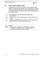
Страница 30: ...e it does not sound at the time of reverse rotation and attainment of the torque limit value 1 Keep holding down both buttons of the PROGRAM key simultaneously 2 The alarm mark on the LCD panel changes and the sound volume changes 3 Release the PROGRAM key when the sound volume reaches your required level and the required sound level is set up NOTICE The sound level is retained even if the power i...

Страница 31: ... with a cotton cloth moistened with soap and water 8 4 Cleaning AC Adapter When the AC adapter becomes dirty disconnect it from the power supply and wipe it off with a cotton cloth moistened with soap and water Lubricate the contra angle head only After each use and or before each autoclaving Screw the spray nozzle onto the Spray can by approx 10 turns Insert the spray nozzle into the rear part of...

Страница 32: ...or lean it in the proper position for gravity draining Mount it after excess oil has been drained Hold the contra angle head securely to prevent it from flying off by the pressure of the spray Supply lubricant until it comes out of the handpiece head for approx 2 seconds Do not use a spray can upside down In such a case only spray gas comes out and oil is not sprayed Do not clean any plastic compo...

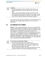
Страница 33: ...TTERIES Note that Dentsply Sirona shall not be held liable for any malfunction or failure resulting from your not following the CAUTIONS ON CHANGING BATTERIES CAUTION Do not apply high temperature sterilization methods such as autoclave sterilization to any part other than the contra angle head Skip dry cycle if the temperature could exceed 135 C 275 F Since the bottom tray inside the chamber of t...

Страница 34: ...ure removal of the AC adapter before changing batteries as it may cause a malfunction 3 Take out the old batteries and pull out the cord holding it at the connector CAUTION Ensure you pull out the cord by holding the connector Failure to do so may cause a break in the cord 4 Insert the connector of the cord of new batteries into the connector in accordance with the polarity indication label inside...

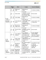
Страница 35: ...e is displayed If the same error code is displayed take action by referring to the instructions provided in the Check Remedy column in the following table CAUTION In case of difficult to insert the connector onto the battery the polarity may be incorrect Do not insert it by force 5 Close the battery cover Ensure you charge the batteries before use NOTICE The used nickel metal hydride batteries are...

Страница 36: ...e locks up The motor handpiece is locked at the time of startup Remove load At the time of charging Low voltage of batteries The voltage of batteries is too low the batteries are flat or not inserted Put the batteries into the battery chamber or replace with new batteries High voltage of batteries The voltage of batteries is too high malfunction of circuit Contact your dealer Beyond the range of w...

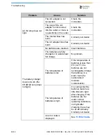
Страница 37: ...ries generate abnormal heat Replace the batteries If the heat generates from the new set of batteries malfunction of the circuit may be suspected Contact your dealer Error code Error Cause Check Remedy Problem Cause Solution The power is not turned on The AC adapter is not connected Check the connection The plug of the AC adapter is not inserted into the outlet or there is no electricity in the ou...

Страница 38: ...ht No batteries are inserted Insert batteries The batteries are fully charged or in a state near full charge No problem The temperature of batteries is low If the temperature of batteries is less than 0 C 32 F the batteries are not rechargeable Charge the batteries in a warm room be careful about moisture condensation The temperature of batteries is high It is normal that the batteries become a li...

Страница 39: ...otor handpiece cord Contact your dealer The motor handpiece does not rotate and the rotation speed are displayed alternately The contra angle head is clogged Clean or replace the contra angle head There is a short circuit inside the motor handpiece or the motor handpiece cord Contact your dealer When turning on the power the alarm sounds and the motor handpiece does not rotate The power is turned ...

Страница 40: ...ails within 30 days from the date of installation immediately contact your dealer have relevant proof of purchase ready 14 DISPOSING PRODUCT PLEASE DO NOT THROW AWAY This product and all its components must absolutely be recycled through your supplier The motor handpiece keeps rotating the foot pedal Optional does not react It is rotated by the ON OFF button Stop the rotation by the ON OFF button ...

Страница 41: ...ass II equipment Type B applied part Caution Follow instructions for use Recycling PLEASE DO NOT THROW AWAY this product and all its components must absolutely be recycled through your supplier Direct current Input current Output current Foot pedal Motor handpiece Autoclavable up to Max 135 C 275 F Short circuit proof safety isolating transformer SN input output ...

Страница 42: ...ed States and is accredited by the Standards Council of Canada to certify electro medical products with Canadian National Standards Marking on the outside of Equipment or Equipment parts that include RF transmitters or that apply RF electromagnetic energy for diagnosis or treatment Opened packages are not replaced Can not be sold separately CE Mark This product meets UL safety standard requirement...

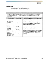
Страница 43: ...agnetic environment guidance RF Emissions CISPR 11 Group 1 The device uses RF energy only for its internal function Therefore its RF emissions are very low and are not likely to cause any interference in nearby electronic equipment RF Emissions CISPR 11 Class B The device is suitable for use in all establishments including domestic establishments and those directly connected to the public low volt...

Страница 44: ...1 kV line s to line s 2 kV line s to earth 1 kV line s to line s 2 kV line s to earth Mains power quality should be that of a typical commercial or hospital environment Voltage dips short interruptions and voltage variations on power supply input lines IEC 61000 4 11 5 UT 95 dip in UT for 0 5 cycle 40 UT 60 dip in UT for 5 cycles 70 UT 30 dip in UT for 25 cycles 5 UT 95 dip in UT for 5 sec 5 UT 95...

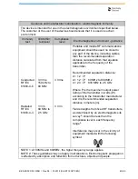
Страница 45: ...ended separation distance calculated from that equation applicable to the frequency of the transmitter Recommended separation distance d 1 2 P d 1 2 P 80 MHz to 800 MHz d 2 3 P 800 MHz to 2 5 GHz Where P is the maximum output power rating of the transmitter in watts W according to the transmitter manufacturer and d is the recommended separation distance in meters m Field strengths from fixed RF tr...

Страница 46: ...verity normal operation If abnormal performance is observed additional measures may be necessary such as reorienting or relocating the device b Over the frequency range 150 kHz to 80 MHz field strengths should be less than 3 V m Cables and accessories Maximum length Complies with Motor Handpiece cord 1 5 m RF emissions CISPR11 Class B Group 1 Harmonic emissions IEC 61000 3 2 Class A Foot Pedal cor...

Страница 47: ...transmitter W Separation distance according to frequency of transmitter m 150 kHz to 80 MHz d 1 2 P 80 MHz to 800 MHz d 1 2 P 800 MHz to 2 5 GHz d 2 3 P 0 01 0 12 0 12 0 23 0 1 0 38 0 38 0 73 1 1 2 1 2 2 3 10 3 8 3 8 7 3 100 12 12 23 For transmitters rated at a maximum output power not listed above the recommended separation distance d in meters m can be estimated using the equation applicable to ...

Страница 48: ...B EN XS00 DFU WEB Rev 08 01 2018 Old ZF 190270 EN dentsplysirona com Maillefer Instruments Holding Sàrl Chemin du Verger 3 CH 1338 Ballaigues Switzerland email endo dentsplysirona com 0086 ...

Отзывы: