Demco Kar Kaddy X Скачать руководство пользователя страница 25

RD20026

Page 25

1.  Place the main frame (#29) on blocks or some other sturdy support so that the 

frame rests approximately 8” - 10” off the ground.

2.  With an assistant, place tongue assembly (#26) into main frame channel and 

position latch on tongue approximately 3” from front of channel. Clamp tongue 

to main frame and support front of tongue.

3.  Locate the four bullet connectors extending out the back of the tongue and 

plug into the connector protruding from under the main frame channel. Plug 

into the flat four connector by matching the colors. Do not cross colors when 

making this connection.   

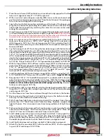
4.  Using the open end of a 9/16” wrench to support the back of the male coupler, 

(as shown below) push drip free quick couplers together. 

NOTE:

 When pushing 

the male connector into the female connector, the female knurl collar will snap 

towards male connector automatically, locking the connection.

5.  With an assistant, mount the tongue assembly (#26) to the front of the tow 

dolly main frame and use a 5/8” x 4-1/2” grade 5 bolt (#13) and lock nut 

(#15) (torque to  50 ft. lbs).  Do not torque over 50 ft. lbs. or bed will not tilt.  

NOTE: Brake line and wiring must be above bolt also coupler assembly must 

be ahead of bolt. 

6.  Lay the bracing struts (#17) out along the tow dolly tongue with the back end 

(the end with the larger hole in it) of the bracing strut toward the main frame.  

Loosely bolt the back of each bracing strut to the trailer frame as shown using 

1/2” x 1-1/2” grade 5 bolt (#8), flatwasher (#2), pivot bushing (#14) and locknut 

(#10).  Hold up the front end (the end with the smaller hole) of each bracing 

strut to the tongue and secure with two 5/8” x 1-1/4” epoxied hex head bolts 

(#18) and nut plate (#25).  Torque the 1/2” x 1-1/2” bolt with the pivot bushing 

to 75 ft. lbs.  Torque the two 5/8” x 1-1/4” epoxied hex head bolts to 100 ft. lbs.

7.  With the top platform (#27) off from undercarriage (#29) and the back wear 

plate screw (#24) removed, attach the tilt bed ramps (#28) as shown using two 

7/16” x 1” grade 8 bolts (#19) and lock nuts (#20) on top of each ramp, and 

four, two on each side of the ramp of 1/2” x 1-1/4” bolts (#7) and 1/2” nylon 

lock nuts (#10).  Reinstall back wear plate screw (#24). 

8.  Install top platform (#27) onto Undercarriage (#29) and fasten using the 3/4” x 

5-1/2” bolt (#22), 3/4” flat washer (#5) and 3/4” lock nut (#4). 

Torque to 100 ft. lbs

9.  Remove the 7/16” x 1-1/4” bolt (#9), flatwasher (#1), and locknut (#11) from the 

outer front panel of each wheel platform tire stop.  Slide the tie-down winch 

(#30) into the channel at the front of the wheel platforms as shown.   

The ratchet 

handles are to the outside of each winch and ratchet springs are to the top.  

Reinstall 

fasteners and torque to 50 ft. lbs.

10.  Install fenders (#31) on tow dolly by installing fender backing plate (#21) and 

three 3/8 x 1-1/2” bolts (#6).  and put nylon lock nuts (#16) on inside of fender 

and torque to 30 ft. lbs.

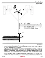
11.  Fish the three wires from the mainframe through the rear hole in the fender.
12.  Route wiring in through back of tail light housing on the bottom inside of 

housing.  Fish the three wire inside of housing.

13.  Pull all wire from light hole in housing and install the snapper hose clip ap-

proximately 1-1/2” back from end of wire shielding.  Squeeze snapper clip 

tight with pliers.  This is to prevent wires from being pulled out of light hous-

ing.

14.  Push wires back into housing and finish routing wires in wire trough of fender 

and attach cable hanger.  Install two metal wire clips using pliers.  Place one 

clip 5-1/2” from rear of fender and one 8” from rear of fender.

15.  Install rubber grommet, plug in wiring to light and attach 3 wire pigtail har-

ness to fender wiring.  NOTE:  On the left side, plug in the bullet plugs with 

white to white, black to brown, and yellow to red.  On the right side, plug in 

the bullet plugs with white to white, black to brown, and green to red.

16.  Install light into grommet, making sure light is fully seated in grommet.
17.  Attach the tire/rim assembly (#23) to the mainframe (#29).  Use the supplied 

lug nuts (#12) and torque to 120 ft lbs.

Female Coupler

Male Coupler

9/16 Wrench

Boxed Tow Dolly Assembly Instructions

Assembly Instructions

Содержание Kar Kaddy X

Страница 1: ...RD20026 Rev 6 08 20 TOW DOLLY Kar Kaddy X...

Страница 2: ...a group of vehicles it may order a recall and remedy campaign However NHTSA cannot become involved in individual problems between you your dealer or DEMCO To contact NHTSA you may either call the Auto...

Страница 3: ...th Street Boyden IA 51234 ph 712 725 2311 Toll Free 1 800 543 3626 Fax 712 725 2380 http www demco products com Equipment Safety Guidelines SAFETY YOU CAN LIVE WITH IT Every year many accidents occur...

Страница 4: ...result in a serious injury or death Do not attempt to mount a tire unless you have the proper equipment and experience to do the job Inflating or servicing tires can be dangerous Whenever possible tr...

Страница 5: ...ed As a precaution always recheck the hardware on equipment following every 100 hours of operation Correct all problems Follow the maintenance safety procedures Highway and Transport Operations Follow...

Страница 6: ...elds and guards after servicing and before moving After servicing be sure all tools parts and service equipment are removed Do not allow grease or oil to build up on the actuator any step or platform...

Страница 7: ...at they are tight The strap on the optional winch must be in good condition and should be wound neatly on winch when not in use NOTE The winch strap must not be left connected to the towed vehicle aft...

Страница 8: ...ey are in good condition Check wheel nuts every trip To check the towing system after hook up tow about 100 feet Then stop and perform a safety check Check the bolts chains tire straps ramps coupler l...

Страница 9: ...lb ft N m 1 4 6 8 9 12 12 16 5 16 10 13 18 25 25 35 3 8 20 27 30 40 45 60 7 16 30 40 50 70 80 110 1 2 45 60 75 100 115 155 9 16 70 95 115 155 165 220 5 8 95 130 150 200 225 300 3 4 165 225 290 390 40...

Страница 10: ...gger C push down and pull all excessstrapfromwinch Laytirestraptooutsideoftowdolly Tighten straps Place tire straps over tires centering straps and winches to tires Whiletighteningstraps pullcrossstra...

Страница 11: ...nnection to the towing vehicle Keep the cable connection at the towing vehicle as centered as possible allow some slack for turning Read these instructions completely before hooking unhooking or using...

Страница 12: ...on each side of the platform and platform returns to original level and locked position Place towed vehicle in park or in gear and fully engage parking brake Towed vehicle tires must fit in wheel trou...

Страница 13: ...s of a standard size that will fit most tires however if your tires are too large or too small you will want to exchange these new straps for the proper size straps 1 Tire too large This is very obvio...

Страница 14: ...essary to cap the transmission tail shaft to prevent transmission fluid loss Rear engine transaxle vehicles cannot be towed with a tow dolly ALL VEHICLES MOUNTED ON THE TOW DOLLY MUST BE MOUNTED WITH...

Страница 15: ...LON LOCK 4 14 02802 NUT 313 NC NYLON LOCK 1 15 03379 LATCH BLOCK 1 16 03381 LATCH CATCH 1 17 03382 LATCH HANDLE BUSHING 1 Please order replacement parts by PART NO DESCRIPTION ITEM PART DESCRIPTION Qt...

Страница 16: ...GR8 EPOXY 8 8 02592 NUT 375NC NYLON LOCK 6 9 03927 10 ROTOR 2 10 04167 BOLT 438NF X 1 00 GR8 HEX 4 11 04168 NUT 434NF NYLON INSERT LOCK 4 12 04174 WASHER DRUM RETAINER 12MM 4 13 04369 5 BOLT HUB SPIN...

Страница 17: ...LT 438NC X 1 25 GR5 HEX 4 3 02771 NUT 438NC NYLON LOCK INSERT 4 4 02383 36 SAFETY CHAIN FOR TOW DOLLIES 2 5 03528 STRAP SHORT 3 POINT TIE DOWN 2 6 12293 1 25 ID X 1 25 PLASTIC BUSHING 1 7 16675 76 TOP...

Страница 18: ...2 WASHER FLAT 75 1 4 01254 BOLT 50NC X 1 50 GR5 HEX 2 5 02178 NUT 50NC LOCK NY INSERT 2 6 02434 BOLT 625NC X 4 50 HEX HEAD GR 5 1 7 02579 BUSHING SPACER PIVOT 2 8 02587 NUT 625 NC NYLON LOCK 1 9 03394...

Страница 19: ...to make sure wire colors are not crossed at that point If plug connection is correct correct problem by reversing yellow and green wire connection on the towing vehicle 4 CAUTION Many flashers for ve...

Страница 20: ...the surface of the fluid Be sure to close bleeder screw securely Repeat bleeding operation at each caliper During the bleeding process replenish the brake fluid so the level does not fall below the 1...

Страница 21: ...OT 1 12 05693 95 SPRING SAFETY LEVER 1 13 05951 EMERGENCY LEVER 1 14 05961 BOLT 313NC X 625 GR5 HEX 2 Please order replacement parts by PART NO DESCRIPTION ITEM PART DESCRIPTION Qty 15 05977 PUSH ROD...

Страница 22: ...er Assembly Shown 1 04425 Tinnerman U clamp 2 2 04508 Amber Reflector not shown 1 04804 Red Reflector not shown 1 3 14722 3 16 x 1 2 Pop Rivet 9 4 05443 Nylon Cable Hanger 1 5 11209 4 LED Tail Light 1...

Страница 23: ...WL 2 5 02772 NUT 25NC LOCK NYLON INSERT 2 6 03574 95 PLATED RATCHET HANDLE 1 7 03578 313 X 50 SHOULDER BOLT 1 8 05337 PIN SAFETY LOCK w CABLE 1 9 05444 BOLT 375NC X 75 HEX HEAD EPOXY 1 10 05449 BUSHIN...

Страница 24: ...Page 24 RD20026 10 3 20 28 19 27 24 7 22 21 6 4 15 13 11 30 1 10 9 29 25 8 2 14 16 17 18 5 26 23 31 12 Parts View Assembly Instructions...

Страница 25: ...using two 7 16 x 1 grade 8 bolts 19 and lock nuts 20 on top of each ramp and four two on each side of the ramp of 1 2 x 1 1 4 bolts 7 and 1 2 nylon lock nuts 10 Reinstall back wear plate screw 24 8 In...

Страница 26: ...3 1 5 6 ITEM PART DESCRIPTION QTY KK2W Optional Winch 1 1 04620 WINCH MECHANISM 1400 CAPACITY 1 04621 REPLACEMENT HANDLE 2 01738 STRAP ASSEMBLY includes strap hook 1 3 02207 BOLT 3 8 16UNC X 3 HEX HEA...

Страница 27: ...10136 RETAINER BUTTON 4 11 10183 SCREW 25 NC X 50 PHILLIPS HEAD 17 12 10184 SCREW 25 NC X 75 PHILLIPS HEAD 4 13 10185 SCREW 25 NC X 1 00 PHILLIPS HEAD 4 14 10186 T NUT 25 NC X 41 BARREL 23 15 11264 SC...

Страница 28: ......

Отзывы: