www.deltapowersolutions.com
6 / 8
NOTE:
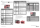
Please read the columns A, B and C together to understand the LCD
information, such as input voltage, estimated remaining backup time, etc.
Column A
Meaning
Column C
Meaning
The 7-segment
display shows
readings or words.
AH
Ampere hour
Column B
Meaning
V
Voltage
SET
Setup mode
%
Percentage
IN
Input
Hz
Frequency
OUT
Output
KVA
kVA
BATT
Battery
KW
kW
LOAD
Load
MIN
Minute
TEST
Test
°C
The UPS’s internal
temperature
6.5 16-segment Display
Hz
KW
KVA
AH
MIN
MIN
ECO
V
V%
IN
SET IN OUT BATT
RUN TIME
°C
LOAD TEST
Display
Meaning
The 16-segment display shows numbers or error codes.
IN
Input
RUN TIME
Estimated remaining backup time.
V
Voltage
MIN
Minute
NOTE:
*
1
In standby mode or in bypass mode, if you change the '
AST
' setting
from '
OFF
' to '
ON
' and execute the step
5
to confirm such change,
the UPS will exit from the setup mode and run in '
Auto-Start to On-line
'
mode right away.
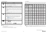
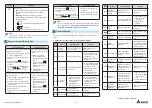
6.3 LCD Display
Hz
KW
KVA
AH
MIN
MIN
ECO
V
V%
IN
SET IN OUT BATT
RUN TIME
°C
LOAD TEST
Icon(s)
Naming
Description
AC Icon
Indicates the input power status.
1.
ON
: Within the acceptable bypass range.
2.
Flashing
: Out of the acceptable bypass
range but sufficient to let the UPS operate
in on-line mode.
3.
OFF
: Out of the acceptable bypass range
and not sufficient to let the UPS operate in
on-line mode.
Output Icon
Indicates the output status.
1.
ON
: There is output.
2.
OFF
: There is no output.
Battery Power
Icon
Indicates the battery power status.
1.
ON
: The battery power is on.
2.
OFF
: The output is not supplied by the
batteries.
ECO
Standby Mode
Graph
Illuminates when the UPS is operating in
standby mode.
ECO
On-line Mode
Graph
Illuminates when the UPS is operating in
on-line mode.
ECO
Battery Mode
Graph
Illuminates when the UPS is operating in
battery mode.
ECO
ECO Mode
Graph
Illuminates when the UPS is operating in
ECO mode.
ECO
Frequency
Converter
Mode
Illuminates when the UPS is operating in
frequency converter mode (the icon
ECO
will flash while these two icons
&
remain on).
Icon(s)
Naming
Description
ECO
Bypass Mode
Graph
Illuminates when the UPS is operating in bypass
mode.
ECO Mode
Illuminates when the UPS is operating in ECO
mode.
1.
ON
: ECO function is enabled and the
connected loads are fed by the utility AC power.
2.
Flashing
: ECO function is enabled and
the connected loads are fed by the double
conversion.
Buzzer Off
Icon
Illuminates when the buzzer is disabled.
Load Level
Bar Graph
Indicates the load level status.
ON
: load level (%)
*
1
.
NOTE:
When the UPS is overloaded,
the warning icon
will flash and the
7-segment display will flash with a load
level value.
Battery Level
Bar Graph
Indicates the battery level status.
1.
ON
( ): The remaining battery capacity (%)
*
1
.
2.
Flashing
( ): Low battery.
3.
Flashing
(
Hz
KW
KVA
AH
MIN
V
%
SET IN OUT BATT
°C
LOAD
TEST
): There is no battery or battery
replacement is required
*
2
.
NOTE:
1.
*
1
means that:
1%~25%: the 1st segment will illuminate.
26%~50%: the first two segments will illuminate.
51%~75%: the first three segments will illuminate.
76%~100%: all segments will illuminate.
2.
*
2
If you need to replace the batteries or the Delta external battery pack(s),
please contact service personnel.
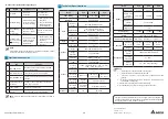
6.4 7-segment Display
Hz
KW
KVA
AH
MIN
MIN
ECO
V
V%
IN
SET IN OUT BATT
RUN TIME
°C
LOAD TEST
Hz
KW
KVA
AH
MIN
MIN
ECO
V
V%
SET IN OUT BATT
°C
LOAD TEST
7-segment Display
Column A Column C
Column B
Continue to the Next Page


