3
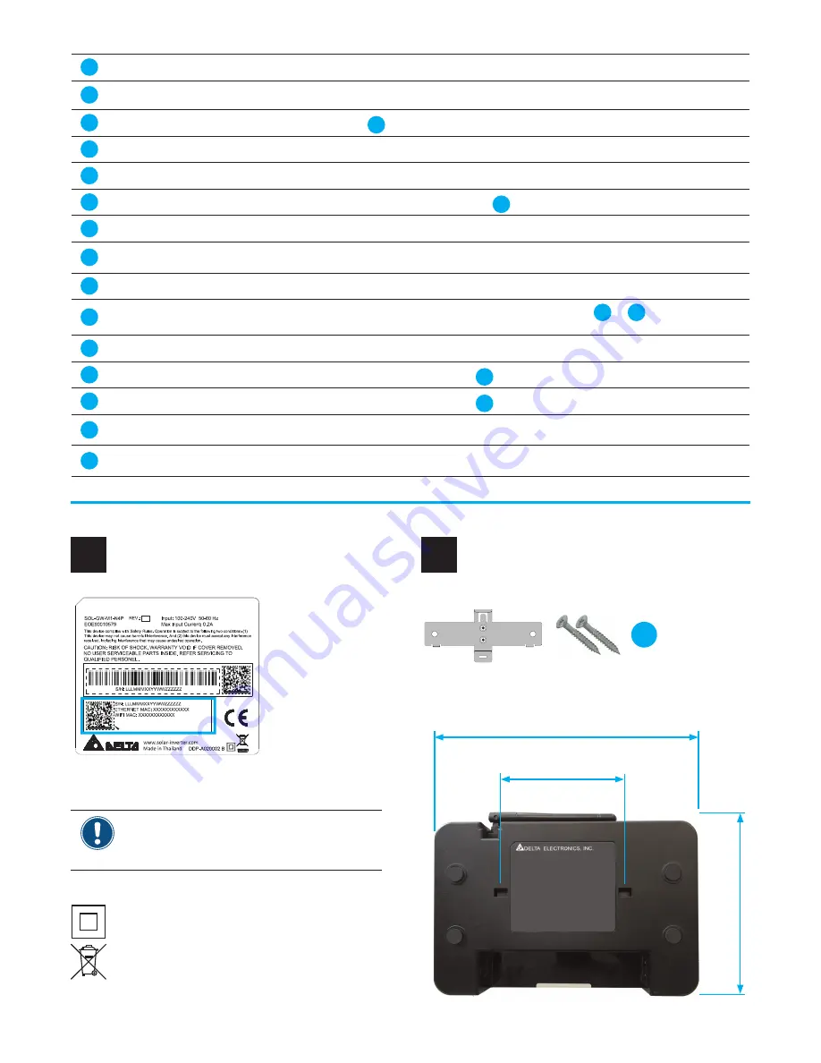
The Gateway is protection class II.
Do not put the Gateway into household waste.
Type label
3
Mounting the Gateway
4
SOLIVIA
nano
GW
15
1
WLAN Antenna
To connect the Gateway wirelessly (WiFi) to a local network or a PC.
2
Display
To show the basic information for the Gateway.
3
MENU button
To awake the
Display
2
from sleep mode and to enter the menu on the
Display
.
4
SCROLL button
To move up and down in the menu and to set a parameter value.
5
ENTER button
To fi nish parameter settings on the display.
6
Mounting holes
To mount the Gateway to the mounting bracket
15
.
7
Ethernet connector
To connect the Gateway to a local network or PC.
8
Type label
Contains important information, e.g. the two MAC addresses which you need for SOLIVIA Moni-
tor.
9
Warranty label
Do not remove. Otherwise you will lose warranty.
10
Power connector
To provide the supply power for the Gateway. Via the
Power cords
12
or
13
, the Gateway com-
municates with the Micro inverters to get their data.
11
RESET button
To return to default settings and restart the Gateway.
12
Power cord EU
To connect the Gateway to the
Wall socket
18
in EU countries.
13
Power cord UK
To connect the Gateway to the
Wall socket
18
in UK.
14
Ethernet cable RJ45
To connect the Gateway to a local network or PC. Not included in the box. Not needed when you
use WiFi.
15
Mounting b 2 x
tapping screws
To mount the Gateway to the wall. Mounting bracket is in the box; screws are not. Use screws
appropriate for the type of wall.
Before you install the Gateway, write down the
two MAC addresses on the type label. You need
them to register your PV plant on SOLIVIA Moni-
tor.
126.0 mm
80.0 mm
172.4 mm
Mounting b
2 x Tapping screws


