169
60
60
50
174
78
72
67
227
unit: mm
7. Installation &
Communication Wiring
SUB_1G
Inverter
comm. module
Red
Black
White
Green
VCC
GND
D+
D-
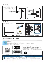
■ Install SUB_1G to inverter.
■
Refer the figure and connect each wire to the communication
card of inverter.
* Screw torque required for
assembling: 1.6 N.m
4. Specifications
ELECTRONIC SPEC
Operating voltage range
Power Consumption
COMMUNICATION
Wired
Wireless
REGUL
A
TION
Safety Standard
Emission (EMI)
CONNECTION
GENERAL INFORMATION
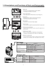
LED Display
Operation temperature
Relative humidity
Dimension (WxHxD)
Weight
PPM N2
_
SB1
12 Vdc
2 Watt
RS-485
SUB_1G
EN 61010-1, CE compliance
EN 300 220 (below 1G), EN 50385, LP0002, Part 15C, Telec T66
Immunity(EMS)
I/O Port
EN 301 489-1/-3, EN 55024, EN 55032, FCC Part 15B
2 pin terminal block for RS-485
Power, SUB_1GHz
-25°C ~ 55°C
30% ~ 85%
78 x 396 x 72 mm
150g
5. Dimensions
6. SUB
_
1G (N2) Module
Modulation techniques
Bandwidth
Explanation
Name
Network standard support
FCC/CE/TELEC/NCC
5860bps (BW: 500kHz)
2930bps (BW: 250kHz)
FSK/OOK
FCC: 500kHz
CE: 250kHz
TELEC: 500kHz
NCC: 500kHz
Data rates
22


