background image

4

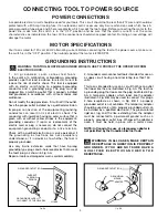
CONNECTING TOOL TO POWER SOURCE

POWER CONNECTIONS

A separate electrical circuit should be used for your tools. This circuit should not be less than #12 wire and should be
protected with a 20 Amp time lag fuse. If an extension cord is used, use only 3-wire extension cords which have 3-
prong grounding type plugs and 3-hole receptacles which accept the tool’s plug. Before connecting the motor to the
power line, make sure the switch is in the “OFF” position and be sure that the electric current is of the same
characteristics as indicated on the tool. All line connections should make good contact. Running on low voltage will
damage the motor.

MOTOR SPECIFICATIONS

Your tool is wired for 120 volt, 60 HZ alternating current. Before connecting the tool to the power source, make sure
the switch is in the “OFF” position. The no-load speed of the motor is 8000 RPM.

GROUNDING INSTRUCTIONS

WARNING: THIS TOOL MUST BE GROUNDED WHILE IN USE TO PROTECT THE OPERATOR FROM
ELECTRIC SHOCK.    

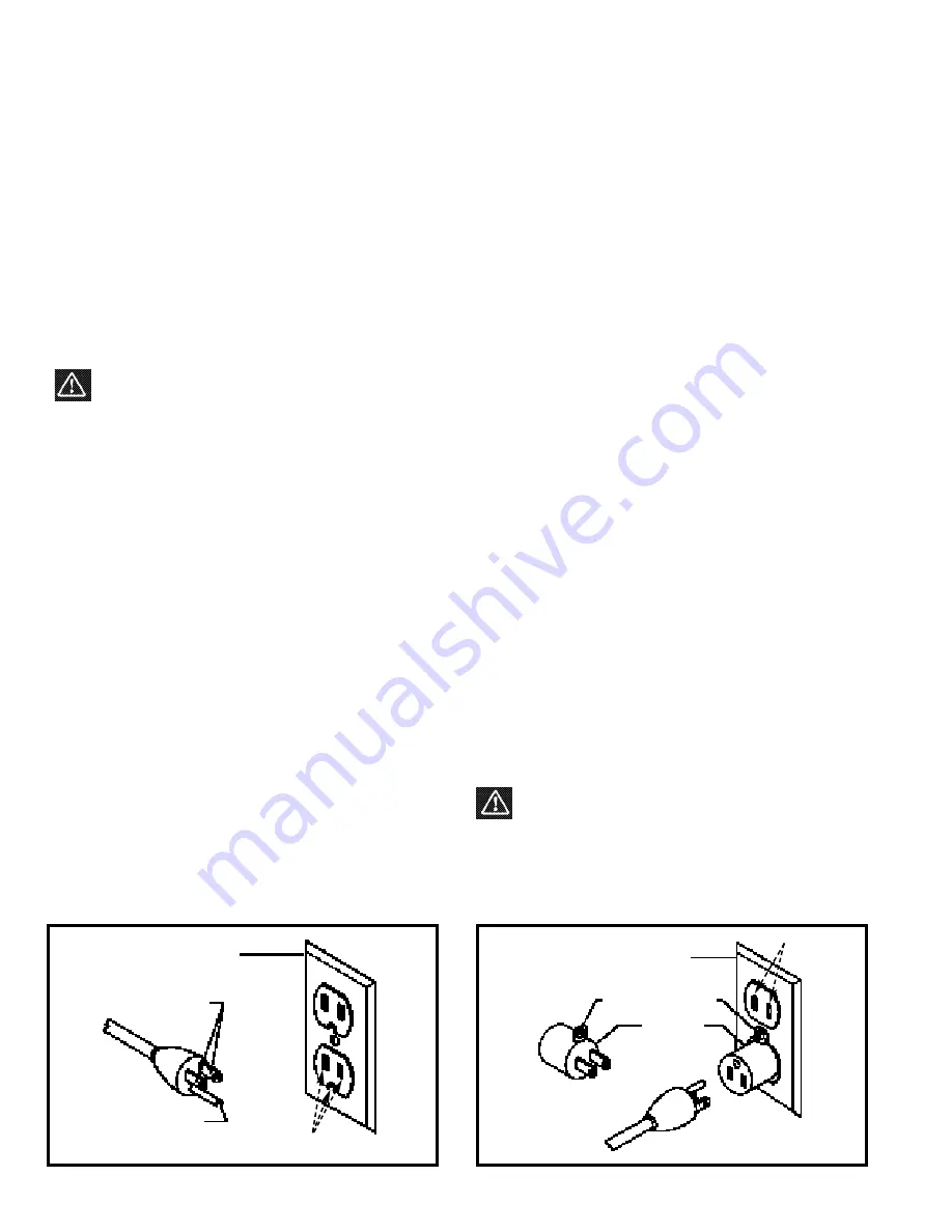
Fig. AA

Fig. BB

GROUNDED OUTLET BOX

CURRENT

CARRYING

PRONGS

GROUNDING BLADE
IS LONGEST OF THE 3 BLADES

GROUNDED OUTLET BOX

GROUNDING

MEANS

ADAPTER

2. Grounded, cord-connected tools intended for use on
a supply circuit having a nominal rating less than 150
volts:

This tool is intended for use on a circuit that has an outlet
that looks like the one illustrated in Fig. AA. The tool has
a grounding plug that looks like the plug illustrated in Fig.
AA

A temporary adapter, which looks like the adapter

illustrated in Fig. BB, may be used to connect this plug a
2-hole receptacle as shown in Fig. BB if a properly
grounded outlet is not available. The temporary adapter
should be used only until a properly grounded outlet can
be installed by a qualified electrician. The green-colored
rigid ear, lug, and the like, extending from the adapter
must be connected to a permanent ground such as a
properly grounded outlet box. Whenever the adapter is
used, it must be held in place with a metal screw.

NOTE: In Canada, the use of a temporary adapter is
not permitted by the Canadian Electric Code.

WARNING: IN ALL CASES, MAKE CERTAIN
RECEPTACLE IN QUESTION IS PROPERLY

G R O U N D E D . I F Y O U A R E N O T S U R E H AV E A
Q U A L I F I E D E L E C T R I C I A N C H E C K T H E
RECEPTACLE.

1 .

A l l g r o u n d e d , c o r d - c o n n e c t e d t o o l s :  

In the event of a malfunction or breakdown, grounding
provides a path of least resistance for electric current to
reduce the risk of electric shock. This tool is equipped
with an electric cord having an equipment-grounding
conductor and a grounding plug. The plug must be
plugged into a matching outlet that is properly installed
and grounded in accordance with all local codes and
ordinances.

Do not modify the plug provided - if it will not fit the outlet,
have the proper outlet installed by a qualified electrician.

Improper connection of the equipment-grounding
conductor can result in risk of electric shock. The
conductor with insulation having an outer surface that is
green with or without yellow stripes is the equipment-
grounding conductor. If repair or replacement of the
electric cord or plug is necessary, do not connect the
equipment-grounding conductor to a live terminal.

Check with a qualified electrician or service personnel if
t h e g ro u n d i n g i n s t r u c t i o n s a re n o t c o m p l e t e l y
understood, or if in doubt as to whether the tool is
properly grounded.

Use only 3-wire extension cords that have 3-prong
grounding type plugs and 3-hole receptacles that accept
the tool’s plug, as shown in Fig. AA.

Repair or replace damaged or worn cord immediately.

HOLES

HOLES

Содержание 22-540

Страница 1: ... PART NO 901606 013 Copyright 2001 Delta Machinery ESPAÑOL PÁGINA 17 To learn more about DELTA MACHINERY visit our website at www deltamachinery com For Parts Service Warranty or other Assistance please call 1 800 223 7278 In Canada call 1 800 463 3582 ...

Страница 2: ...stant lenses they are not safety glasses Also use face or dust mask if cutting operation is dusty These safety glasses must conform to ANSI Z87 1 requirements Note Approved glasses have Z87 printed or stamped on them 13 SECURE WORK Use clamps or a vise to hold work when practical It s safer than using your hand and frees both hands to operate tool 14 DON T OVERREACH Keep proper footing and balance...

Страница 3: ...m nails and other foreign objects which could cause injury or damage to the blades 17 MAKE SURE the blades are properly secured in the cutterhead as explained in the instruction manual be fore turning on power 18 ALWAYS allow the cutterhead to reach full speed before using 19 IF DURING OPERATION there is any tendency for the tool to tip over slide or walk on the supporting surface MAKE SURE TOOL I...

Страница 4: ...unded outlet can be installed by a qualified electrician The green colored rigid ear lug and the like extending from the adapter must be connected to a permanent ground such as a properly grounded outlet box Whenever the adapter is used it must be held in place with a metal screw NOTE In Canada the use of a temporary adapter is not permitted by the Canadian Electric Code WARNING IN ALL CASES MAKE ...

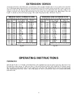
Страница 5: ...ting gage and wrench polyurethane feed rolls and adjustable folding table extensions 5 Fig DD MINIMUM GAUGE EXTENSION CORD RECOMMENDED SIZES FOR USE WITH STATIONARY ELECTRIC TOOLS Ampere Volts Total Length of Gauge of Rating Cord in Feet Extension Cord 0 6 120 up to 25 18 AWG 0 6 120 25 50 16 AWG 0 6 120 50 100 16 AWG 0 6 120 100 150 14 AWG 6 10 120 up to 25 18 AWG 6 10 120 25 50 16 AWG 6 10 120 5...

Страница 6: ... not use acetone gasoline or lacquer thinner for this purpose After cleaning cover the unpainted sufaces with a good quality paste wax CAUTION CARE MUST BE TAKEN WHEN CLEANING THE CUTTERHEAD AS THE KNIVES ARE SHIPPED IN THE CUTTERHEAD AND THEY ARE VERY SHARP Figs 2 and 3 ILLUSTRATE THE PLANER AND ALL LOOSE ITEMS SUPPLIED WITH THE MACHINE 1 12 Planer 2 Chip Deflector Fig 2 Fig 3 3 Knife Setting Gag...

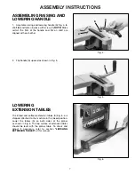
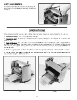
Страница 7: ...aligned with each other 2 Flip handle A upward as shown in Fig 5 LOWERING EXTENSION TABLES The infeed and outfeed extension tables A Fig 6 are shipped attached to the machine in the raised position Lower the tables A on both sides of the planer as shown in Fig 6 The top surface of extension tables should be level with the planer table To check and adjust if necessary refer to section LEVELING EXTE...

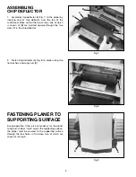
Страница 8: ...d upward through the two slots C in the chip deflector 2 Fasten chip deflector A Fig 8 to planer using two flat washers and wing nuts D FASTENING PLANER TO SUPPORTING SURFACE During operation if there is any tendency for the planer to tip over slide or walk across the supporting surface the planer must be secured to the supporting surface through the four holes in the base two of which are shown a...

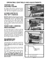
Страница 9: ...olution of the raising and lowering handle B Fig 15 will move the cutterhead up or down 5 64 A 3 32 depth of cut can be made in soft woods on stock 8 wide and in hard woods on stock up to 7 wide See chart Fig 16 For 10 and 12 wide soft wood we recommend a maxi mum depth of cut of 1 16 For 10 and 12 wide hard wood a maximum depth of cut of 3 64 is recommended IMPORTANT A 3 32 DEPTH OF CUT CAN BE MA...

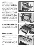
Страница 10: ...oosen two screws F adjust extension table and retighten two screws F Adjust opposite side of the table in the same manner Make certain the extension table is solidly supported when there is downward pressure on the table 3 Check and adjust outfeed extension table in the same manner STORING THE POWER CORD Wire hangers A Fig 18 are provided on the underside of the outfeed extension table as shown to...

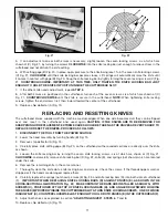
Страница 11: ...CAUTION IF THE KNIVES ARE TO BE REMOVED FOR SHARPENING OR REPLACEMENT EXTREME CARE SHOULD BE TAKEN AS THE KNIVES ARE VERY SHARP TO REPLACE OR RESET THE KNIVES PROCEED AS FOLLOWS 1 DISCONNECT THE TOOL FROM THE POWER SOURCE 2 Lower the head assembly by turning handle B Fig 15 3 Remove chip deflector A Fig 19 4 Carefully place knife setting gage B Fig 20 on the cutterhead so the rounded sections are ...

Страница 12: ...3 Plane to Thickness Place the side you just surfaced in STEP 2 face down and feed the board through the Planer as shown in Figs 24 and 25 Plane both sides of the board until you are satisfied with the thickness making thin cuts with each pass If during the planing operation you notice the board twisting warping or bowing repeat STEP 2 and true up one face 4 When planing long stock provide auxilia...

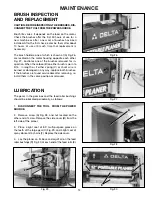
Страница 13: ... the carbon B on either brush is worn to 3 16 in length or if either spring C or shunt wire is burned or damaged in any way replace both brushes If the brushes are found serviceable after removing re install them in the same position as removed LUBRICATION The gears in the gear box and the feed roller bushings should be lubricated periodically as follows 1 DISCONNECT THE TOOL FROM THE POWER SOURCE...

Страница 14: ...elta s sole warranty and sets forth the customer s exclusive remedy with respect to defective products all other warranties express or implied whether of merchantability fitness for purpose or otherwise are expressly disclaimed by Delta PARTS SERVICE OR WARRANTY ASSISTANCE All Delta Machines and accessories are manufactured to high quality standards and are serviced by a network of Porter Cable De...

Страница 15: ...15 NOTES ...

Страница 16: ...16 NOTES ...

Страница 17: ... Teagarden Street Phone 510 357 9762 Fax 510 357 7939 FLORIDA Davie 33314 Miami 4343 South State Rd 7 441 Unit 107 Phone 954 321 6635 Fax 954 321 6638 Tampa 33609 4538 W Kennedy Boulevard Phone 813 877 9585 Fax 813 289 7948 GEORGIA Forest Park 30297 Atlanta 5442 Frontage Road Suite 112 Phone 404 608 0006 Fax 404 608 1123 ILLINOIS Addison 60101 Chicago 311 Laura Drive Phone 630 628 6100 Fax 630 628...

Отзывы: