


Turbo PMAC PCI Lite
Machine Connections
13
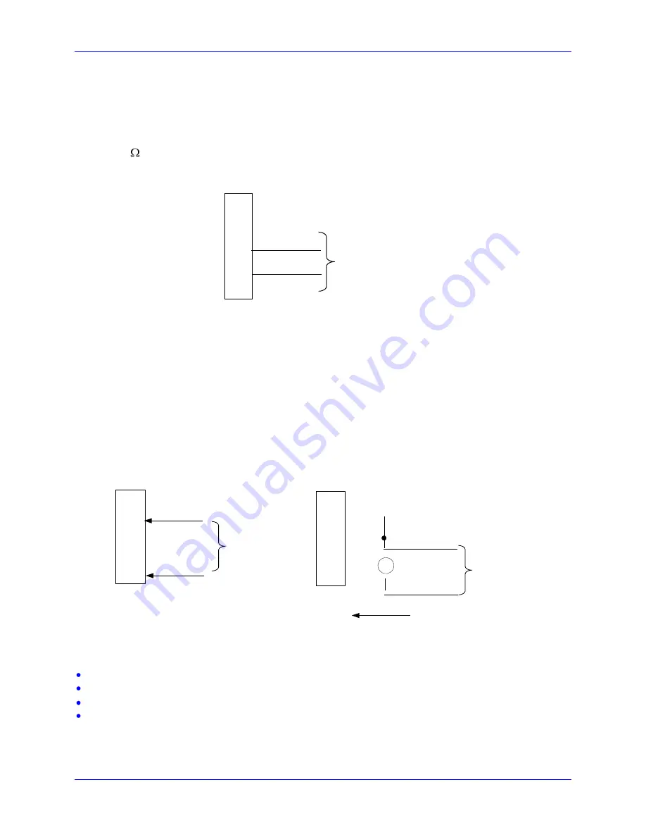
Amplifier Enable Signal (AENAx/DIRn)
Most amplifiers have an enable/disable input that permits complete shutdown of the amplifier regardless
of the voltage of the command signal. PMAC's AENA line is meant for this purpose. If not using a
direction and magnitude amplifier or voltage-to-frequency converter, use this pin to enable and disable
the amplifier (wired to the enable line). AENA1/DIR1 is pin 47. This signal is an open-collector output
with a 3.3 k pull-up resistor to +V, which is a voltage selected by jumper E100. The pull-up resistor
packs are RP43 for channels 1-4. For early tests, this amplifier signal should be under manual control.
This signal could be either sinking or sourcing as determined by chips U37 (see jumpers E100-E102).
For 24 Volts operation E100 must connect pins 2-3 and a separate power supply must be brought on pins
9-7 of the J9 JEQU connector. The polarity of the signal is controlled by jumpers E17A to E17D. The
default is low-true (conducting) enable. In addition, the amplifier enable signal could be manually
controlled setting Ix00=0 and using the suggested definition of the Mx14 variable.
Amplifier Fault Signal (FAULTn)
This input can take a signal from the amplifier so PMAC knows when the amplifier is having problems,
and can shut down action. The polarity is programmable with I-variable Ix25 (I125 for motor #1) and the
return signal is analog ground (AGND). FAULT1 is pin 49. With the default setup, this signal must
actively be pulled low for a fault condition. In this setup, if nothing is wired into this input, PMAC will
consider the motor not to be in a fault condition. The amplifier fault signal could be monitored using the
properly defined Mx23 variable.
Some amplifiers share the amplifier fault output with the amplifier enable\disable status output. In this
case a special PLC code must be written with the following sequence:
Disable the amplifier fault input (see Ix25)
Enable the motor (
J/
command).
Wait for the amplifier fault input to be false (monitor Mx23).
Re-enable the amplifier fault input (see Ix25).
JMACH1
AENA1
AGND
47
58
Connect to the
amplifier enable input
49
FAULT1
AGND
58
Connect to the
amplifier fault
output
JMACH1
49 FAULT1
JEQU, PIN 9
Connect to the
amplifier fault
output
+
-
12-15 Volts signal (E100 on 1-2)
15-24 Volts signal (E100 on 2-3)
1
2
-2
3
V
D
C
Содержание Turbo PMAC PCI-Lite
Страница 4: ......
Страница 8: ......
Страница 32: ...Turbo PMAC PCI Lite 24 Hardware Reference Summary Board Dimensions Part Number 603657 105...


