Delta Elektronika SM15K Series Скачать руководство пользователя страница 8

MASTER SLAVE 


SM15K INTERFACES 

8 / 19 

DELTA ELEKTRONIKA B.V. 

rev. Nov. 2019 


o


The Master has a specific location in the system, depending 
on the number of Slaves. 

o


Although in a later stage the functional assigned is done via 
the unit's menu, it is required to do the physical assignment 
first; at which location will the Master be and at which the 
Slave(s). 

o


For an uneven number of units, position the Master in 
between an equal number of slaves.  

o


For example in a set of 5 units, the upper 2 units must be 
slaves, the master in position 3, and below it another 2 
slaves. 

o


For an even number of units, position the master in such a 
way that under it there's 1 slave more than above it. 

o


For example in a set of 6 units, the upper 2 units must be 
slaves, then the master, and below it another 3 slaves. 

o


See the 

M/S application note

 for more details. 

o


For set-ups with more than 1 rack, position the master as 
described in the above, and fill the other racks with slaves 
only. 


Connect the copper strips. 

o


See example drawings for different number of units in the 

M/S application note

See fig 3 - 2. 

o


Remove safety covers from the DC power terminals. 

o


Remove the M8 bolts from the DC power terminals. 

o


Important: follow the exact order of washers, lock washers, 
etc to ensure correct and safe operation. 


Connect the load cables. 

o


Connect the cable lugs at the position indicated on the 
drawings in the application note. 

o


Place the lugs directly on the strips - never place a washer 
between a cable lug and a copper strip because it will burn 
out. 

o


Place the special M/S parallel safety covers over the output 
terminals.  

o


Cover with marking DWG2532 is for the outputs of the 
upper and lower units. Cover DWG2533 is for units in 
between them. 

o


Create openings for the load cables where necessary. 


Contact factory for systems with more than one rack of units. 
 

3.4.4


CONNECT INTERFACES 


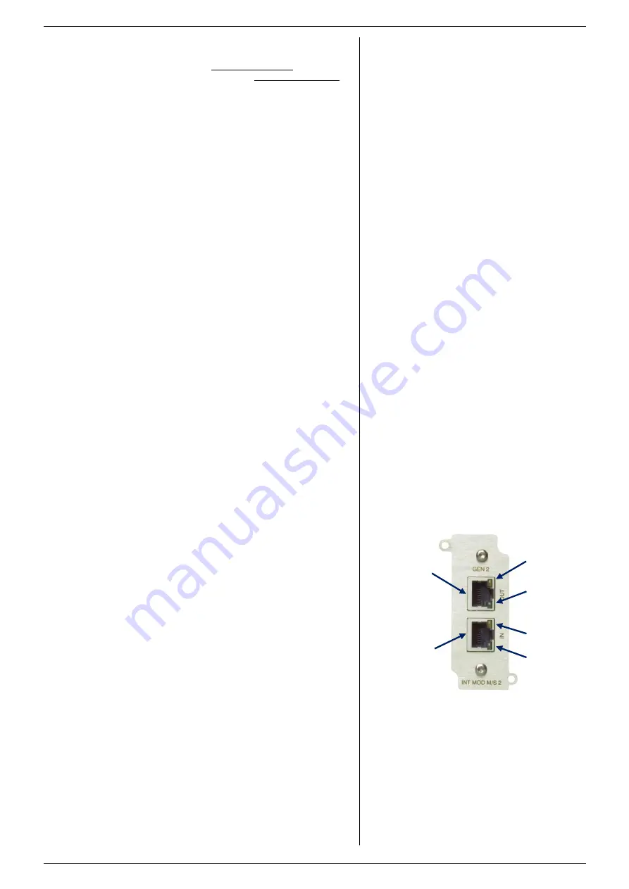
The available connectors on this interface are two 8 pole 
modular jack connectors, see fig. 3 - 3. 


Use the cables supplied with the M/S kit (Cat6, FTP or 
S/FTP). 


Start with the master and connect the cable from the "OUT"  


connector to the "IN" connector of the first slave above.  


Then connect another cable from the "OUT" connector of the 
first slave to the "IN" connector of the next slave. Repeat this 
until all devices are connected. (see fig 3 - 2). 


For systems with 3 or more slaves, use the longer cable (1m 
or 2m depending on amount of slaves) to connect the upper 
unit to the most lower unit. 


From the lower unit, again connect to "IN" of the unit above 


Finally close the loop at the Master unit "IN" connector. 


For more than one rack of units, connect the "OUT" of the 
upper unit to the "IN" of the lower unit in the next rack. In that 
rack connect up until the highest unit is reached. From that 
unit, connect to the "IN" of the  lowest unit of the first rack 
again and there connect up to the master unit to close the 
loop. 
 

3.4.5


CONNECT AC MAINS 


Connect the mains supply cables to the units. 

o


Make sure the cable is not yet connected to the mains 
supply! 

o


Place the input safety covers. 


Connect the mains supply cables to the mains supply. 


fig 3 - 3 

There are two 8-pole modular jack connectors  

available on the INT MOD M/S-2. 

enabled 

Tx active 

Rx active 

valid 

OUT 

IN 

Содержание SM15K Series

Страница 1: ...on P0120 Contents 1 Safety Instructions 2 Sicherheitshinweise 3 Master Slave Interface 4 Isolated Contacts 5 Serial Interface 6 Digital User I O 7 Isolated Analog Interface Firmware Update It is stron...

Страница 2: ...nd either the minus or plus DC power terminal is grounded the voltage on the DC power terminals and sense connections can be considered safe Caution 1 If a low voltage unit has both DC power terminals...

Страница 3: ...covers Safety cover s are used to cover potentially hazardous voltages Observe the following when removing safety cover s Switch off the unit Disconnect the unit from the mains supply or power outlet...

Страница 4: ...als sicher angesehen werden wenn die minus DC Anschlussklemme des Ger ts im Verh ltnis zur Erdung 1000 VDC 707 Vpk nicht berschreitet f r SM70 CP 450 SM210 CP 150 und SM500 CP 90 oder 1500VDC 1060Vpk...

Страница 5: ...ie Folgendes wenn Sie die Sicherheitsabdeckung en entfernen Ger t ausschalten Ger t von dem Versorgungsnetz oder der Stromquelle trennen Warten Sie 5 Minuten damit interne Kondensatoren sich entladen...

Страница 6: ...er In the front menu go to SYSTEM INFO UNIT VERSION If an update is required refer to the SM15K unit manual how to do this 3 4 HARDWARE INSTALLATION Warning Never make connections to the Power Inputs...

Страница 7: ...first insert the bolts with crinkle washers in all DC power terminals Then assemble the entire strip to the DC power terminals This because bolts cannot be inserted in the DC power terminals once the...

Страница 8: ...rip because it will burn out o Place the special M S parallel safety covers over the output terminals o Cover with marking DWG2532 is for the outputs of the upper and lower units Cover DWG2533 is for...

Страница 9: ...own in the display see fig 3 6 The master or slave can also be configured via the web interface or using Ethernet commands After changing master or slave settings stored sequences need to be rebuilt d...

Страница 10: ...how to do this 4 4 HARDWARE INSTALLATION Warning Never make connections to the Power Inputs and Outputs or the Sense Connector when the SM15K unit is connected to the mains supply or power outlet Safe...

Страница 11: ...N M o 6 Relay 1 NC o 5 Relay 1 NO o 4 Relay 1 Common o 3 Relay 2 NC o 2 Relay 2 NO o 1 Relay 2 Common Pinning CON N o 6 Relay 3 NC o 5 Relay 3 NO o 4 Relay 3 Common o 3 Relay 4 NC o 2 Relay 4 NO o 1 R...

Страница 12: ...to the SM15K unit manual how to do this 5 4 HARDWARE INSTALLATION Warning Never make connections to the Power Inputs and Outputs or the Sense Connector when the SM15K unit is connected to the mains su...

Страница 13: ...e monitored Download the manual Ethernet Sequencer Programming SM15K for details 5 9 TROUBLE SHOOTING Check the programming source is set to the correct slot Check the output is switched ON the Interl...

Страница 14: ...the unit must be in CC mode and when programming a power the unit must be in CP mode 5 10 CALIBRATION Calibration of the interface is not applicable 5 11 Settings Settings via the web page o Bus type...

Страница 15: ...red refer to the SM15K unit manual how to do this 6 4 HARDWARE INSTALLATION Warning Never make connections to the Power Inputs and Outputs or the Sense Connector when the SM15K unit is connected to th...

Страница 16: ...pin 15 The user inputs have a working range of 2V 30V use a common zero and have an impedance of approximately 22kOhms The maximum load of the 5V is 100mA See figure 6 4 and table 6 1 for the pinning...

Страница 17: ...mware package is P0120 or higher In the front menu go to SYSTEM INFO UNIT VERSION If an update is required refer to the SM15K unit manual how to do this 7 4 HARDWARE INSTALLATION Warning Never make co...

Страница 18: ...afe value Note that the programming inputs are floating with regards the power output Turn the output on again with the OUTPUT ON OFF button To program the unit by current instead of voltage simply us...

Страница 19: ...ble to use a relay contact or a switch to shut the unit down see fig 7 9 In standby mode the power supply consumes very little power Note also via Eth or other interfaces RSD can be activated 7 10 REF...

Отзывы: