3
A
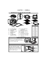
Top heating element
B
Oven light (if fitted)
C
Side guides
D
Third heating element
connector
E
Thermostat knob
F
Pilot light
G
On/off and toast
programming knob
H
Function selector knob
I
Control panel
L
Bottom heating element
M
Glass door
N
Two aluminum beke pans
O
Wire rack
P
Removable heating element
Q
Broiling rack (if provided)
R
Cookie sheet (if provided)
S
Crumb tray
T
Curve wire rack
SIDE GUIDES
The oven has three guides to position
baking pans and wire racks at different
heights. Guide 2 is also used to insert the
removable heating element for the "dou-
ble oven" function, s
ee page 6
.
Guide 1
Guide 2
Guide 3
REMOVABLE HEATING ELEMENT HOUSING
When not in use, the removable heating element
(P) can be placed in the special housing under the
oven as show in the figure right.
CONVERSION TABLE:
°C
°F
120
250
135
275
150
300
163
325
177
350
190
375
205
400
218
425
233
450
240
470
C H A P T E R 1 - G E N E R A L
1.1 - DESCRIPTION OF THE OVEN AND THE ACCESSORIES


