background image

10

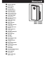
REMOTE CONTROL DESCRIpTION  

  Air conditioning symbol

2   Dehumidifying symbol

  fan symbol

  Heating symbol

  SMArT symbol

6   Signal transmission

  Selected temperature scale indicator

  Relative humidity indicator

9   SLEEP symbol

10  AUTo fan speed indicator

11  fan speed indicator

12  Clock

13  Timer on symbol

14  Timer off symbol

15  MoDe button (selects the modes)

16  on/Standby button

17  fAn button

18  Increase (+) and decrease (-) button

19  Reset button (resets the factory default 


settings)

20  Timer on button

21  SeT button

22  Timer off button

23  SWInG button

24  SLEEP button
25  °C or °f selection button

USING THE REMOTE CONTROL

•   point the remote control at the receiver on


the appliance. The remote control must be


no more than 23 feet away from the 


appliance (without obstacles between the 


remote control and the receiver).

•   The remote control must be handled with


extreme care. Do not drop it or expose it to


direct sunlight or sources of heat.

 
INSERTING OR REpLACING THE BATTERIES

•   remove the cover on the rear of the remote 

control (fig.17);

•   Insert two r03 “AAA” 1.5V batteries in the 

correct position (see instructions inside the 

battery compartment);

•   replace the cover.

  If  the  remote  control  unit  is  replaced  or  di-

scarded, the batteries must be removed and 

disposed  of  in  accordance  with  current  le-

gislation as they are harmful to the environ-

ment. Do not mix old and new batteries. 

  Do not mix alkaline, standard (carbon-zinc) or 

rechargeable (nickel-cadmium) batteries. Do 

not dispose of batteries in fire. Batteries may 

explode or leak. If the remote control is not be 

used for a certain length of time, remove the 

batteries.

Note: This equipment has been tested and found 

to comply with the limits for a Class B digital de-

vice, pursuant to part 15 of the FCC Rules. These 

2

6

9

10

15

19

20

3 4

7

11

14

18

22

25

23

12

1

13

17

16

21

24

8


MAX. 23 feet

17

Содержание PAC T140HPEC

Страница 1: ...of service centers near you U S Only Enregistrez ce produit en ligne et recevez un num ro gratuit de Cook s Illustrated Visitez www delonghiregistration com Visitez www delonghiusa com pour y voir un...

Страница 2: ...ons always unplug the unit from the out let Do not pull on or place strain on the power cord when moving the appliance The appliance should not be installed whe re the atmosphere may contain combu sti...

Страница 3: ...icient heat pump system provides a high heating capacity with low energy consumption All Pinguino models can also be used in fan only mode PREPARING FOR USE The instructions below will enable you to p...

Страница 4: ...ust hose M Air inlet to intake hose N 2 window outlets O Suckers P Castor locks Q Continuous drain hose with coupling R Remote control S 3M air purifying filter T Silver ion filter U Single hole windo...

Страница 5: ...together fig 4 1 2 3 Air conditioning with installation If required your appliance can be installed semi permanently Fig 5 and 5A Proceed as follows Drill a hole in an outside wall or through a windo...

Страница 6: ...guarantee correct ventilation MAX100 cm MIN 35 cm MAX 39 37 inches MIN 13 77 inches control panel 15 14 4 5 6 7 9 13 1 11 12 3 9 2 8 Description 1 ON Standby button on off 2 MODE button selects the m...

Страница 7: ...elects the most appropriate speed Water is removed from the air and collected in the tank at the back of the air conditioner When the tank is full the appliance shuts down and full tank appears on the...

Страница 8: ...e FAN button Three speeds are available Quiet speed for quiet operation High speed for maximum fan po wer Medium speed reduces noise le vels but still maintains a good level of comfort High speed for...

Страница 9: ...e the continuous drain function fit the hose with the rapid coupling as shown in fig 13 With particular weather conditions it is possible that some wet built up in the air exhaust hose L SMART MODE FI...

Страница 10: ...The remote control must be handled with extreme care Do not drop it or expose it to direct sunlight or sources of heat INSERTING OR REPLACING THE BATTERIES Remove the cover on the rear of the remote c...

Страница 11: ...nd 2 this device must ac cept any interference received including inter ference that may cause undesired operation SETTING THE TIME After having inserted the batteries the clock on the display flashes...

Страница 12: ...bute air uniformly throughout the room or to focus air in a certain direction When the SWING button is pressed and the flaps have begun moving alternately forwards and backwards pressing the button ag...

Страница 13: ...ages are displayed on the appliance display IF IS DISPLAYED WHAT SHOULD I DO IF IS DISPLAYED WHAT SHOULD I DO LOW TEMPERATURE frost prevention FULL TANK PROBE FAILURE sensor damaged FAILURE 1 pump fai...

Страница 14: ...ILTER The 3M electrostatic filter retains the finest dust particles thus enhancing the filtering capa city of the appliance To use the 3M electrostatic filter A Remove the intake grille B Remove the f...

Страница 15: ...detaching it from the grille Use a vacuum cleaner to remove dust accumula tions from the silver ion filter If it is very dirty immerse in warm water and rin se a number of times The water should neve...

Страница 16: ...air exhaust hose is detached from the appliance silver ion and 3M filter clogged the technical specification of the appliance is not adequate for the room in which it is located close doors windows an...

Страница 17: ...nded in the accordance with all local codes and ordinances Do not mo dify the plug provided with the appliance If it will not fit the outlet have a proper outlet installed by a qualified electrician o...

Страница 18: ...e owner of the unit This warranty shall apply only if the appliance is used in accordance with the factory directions that accompany it and on an Alternating Current AC circuit This warranty is in lie...

Отзывы: