DeLonghi DL 48 P6G Скачать руководство пользователя страница 16

16

5. Leak Testing:

IMPORTANT: Leak testing of the appliance shall be conducted as follows:

• After final gas connection is made, turn on manual gas valve and test all

connections in gas supply piping and appliance for gas leaks with a soapy water
solution. During this test all appliance gas valves have to be closed.

• In order to avoid property damage or serious personal injury, never use a Iighted

match. If a leak is present, tighten joint or unscrew, apply more joint compound,
tighten again and retest connection for leak.

b) Any conversion required must be performed by your dealer or a qualified licensed

plumber or gas service company. Please provide the service person with this
manual before work is started on the range. (Gas conversions are the responsibility
of the dealer or end user.)

c) This range can be used with NATURAL or LP/PROPANE gas. It is shipped from

the factory adjusted for use with NATURAL gas.

d) Manifold pressure should be checked with a manometer and by operating as below

detailed:

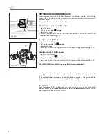
- Remove the injector from the front left burner and mount the proper test point

adapter which is available from the After-Sales Service (see side figure and the
“OPERATIONS TO BE PERFORMED WHEN SUBSTITUTING THE INJECTORS”
chapter).

- Turn the front left burner control knob to the maximum position (

position)

- Press the knob and keeping it pressed check the manifold pressure with a

manometer; NATURAL gas requires 4.0” W.C.P. and LP/PROPANE requires 11.0”
W.C.P.

- Incoming line pressure upstream from the regulator must be 1” W.C.P. higher

than the manifold pressure in order to check the regulator. 

- The regulator used on this range can withstand a maximum input pressure of

1/2 PSI (14.0” W.C.P). If the line pressure is in excess of that amount, a step-
down regulator will be required.

e) The appliance, its individual shut-off valve, and pressure regulator must be

disconnected from the gas supply piping system during any pressure testing of
that system at pressures in excess of 1/2 PSI (3.5 kPa).

f) The appliance must be isolated from the gas supply piping system by closing its

individual manual shut-off valve during any pressure testing of the gas supply
piping system at test pressure equal to or less than 1/2 PSI (3.5 kPa).

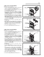
3. Flexible Connections:

If local codes permit, CSA design-certified, flexible metal appliance connector is
recommended for connecting this range to the gas supply line. Do Not kink or damage
the flexible connector when moving the range. The pressure regulator has 1/2" NPT
female pipe threads.You will need to determine the fittings required, depending on
the size of your gas supply line, flexible metal connector and shutoff valve.

Fig. 2.4

4. Rigid Pipe Connections:

If rigid pipe is used as a gas supply line, a combination of pipe fittings must be used
to obtain an in-line connection to the range. All strains must be removed from the
supply and fuel lines so range will be level and in line.

• Use joint compounds and gaskets  that  are resistant to action of natural or

propane gas on all male pipe threads.

• Do not over  tighten gas fitting when attaching to pressure regulator. Over

tightening may crack regulator. 

TEST POINT ADAPTER

The Test Point adapter is available from
the After-Sales Service.

Содержание DL 48 P6G

Страница 1: ...he Manufactured Home Construction and Safety Standard Title 24 CFR Part 3280 for merly the Federal Standard for Mobile Home Construction and Safety Title 24 HUD Part 280 or when such standard is not applicable the Standard for Manufactured Home Installations ANSI NCSBCS A225 1 or with local codes where applicable INSTALLATION IN RECREATIONAL PARK TRAILERS The installation must conform with state o...

Страница 2: ...eighbor s phone Follow the gas supplier s instructions lf you cannot reach your gas supplier call the fire department Installation and service must be performed by a qualified installer service agency or the gas supplier WARNING IF THE INFORMATION IN THIS MANUAL IS NOT FOLLOWED EXACTLY A FIRE OR EXPLOSION MAY RESULT CAUSING PROPERTY DAMAGE PERSONAL INJURY OR DEATH WARNING ALL RANGES CAN TIP INJURY...

Страница 3: ...of domestic household food and in not suitable for any none domestic application and therefore should not be used in a commercial environmement The appliance guarantee will be void if the appliance is used within a none domestic environmement i e a semi commercial commercial or communal environment ...

Страница 4: ...age Consult a qualified installer service agent or the gas supplier IMPORTANT The use of suitable protective clothing gloves is recommended when handling installing of this appliance INSTALLATION INSTRUCTIONS TOOLS NEEDED FOR INSTALLATION Screwdriver 2 Wrench T handle wrench Tape measure Pencil Adjustable pliers Adjustable wrench Suitable protective gloves Drill Hammer ...

Страница 5: ...lly remove the range by pulling outward CAUTION Range is heavy use care in handling 10 Electrical Requirement Electrical installation should comply with national and local codes 11 Air Supply and Ventilation The installer must refers to local national codes 12 Gas Manifold Pressure Natural gas 4 0 W C P LP Propane 11 0 W C P 13 The misuse of oven door e g stepping sitting or leaning on them can re...

Страница 6: ...m 47 7 8 MIN 36 1 64 915 mm MAX 36 1 2 927 mm Fig 1 1a Fig 1 1b 2 The range CANNOT be installed directly adjacent to side walls tall cabinets tall appliances or other side vertical sur faces above 36 914 mm high There must be a minimum of 11 13 16 300 mm side clear ance from the range to such combustible surfaces TO THE LEFT or TO THE RIGHT above the 36 914 mm high coun tertop IMPORTANT One side l...

Страница 7: ...C GAS AND ELECTRIC CONNECTION Dotted line showing the posi tion Depending on feet regulation Area for GAS and ELECTRIC connection Fig 1 2 Rif inch mm A 15 3 4 400 B 2 51 64 71 C 21 32 16 5 D 4 7 32 4 11 16 107 119 ...

Страница 8: ... mm 36 0 0 0 mm 0 mm 20 min 500 mm 11 13 16 min 300 mm 13 max 330 mm 457 mm 18 min 30 min 762 mm 914 mm 36 0 0 mm 0 0 mm 20 min 500 mm 11 13 16 min 300 mm 13 max 330 mm Fig 1 3b Fig 1 3a PROXIMITY TO SIDE CABINETS RANGE WITH BACKGUARD ...

Страница 9: ... 0 mm 20 min 500 mm 13 max 330 mm 11 13 16 min 300 mm 12 min 305 mm 457 mm 18 min 30 min 762 mm 914 mm 36 0 0 mm 0 0 mm 20 min 500 mm 11 13 16 min 300 mm 13 max 330 mm 12 min 305 mm Fig 1 3c Fig 1 3d PROXIMITY TO SIDE CABINETS RANGE WITH ISLAND TRIM ...

Страница 10: ...ig 1 5 ASSEMBLING THE BACKGUARD OR THE ISLAND TRIM It is mandatory to install the backguard or the island trim Assemble the backguard or the island trim as shown in figure 1 4 or 1 5 and fix it by screw ing the 5 screws A ...

Страница 11: ...eady fitted on the appliance and may be levelled by screwing or unscrewing the feet fig 1 9 It is important to observe the prescriptions of figures 1 6 1 7 1 8 5 16 8 mm 5 16 8 mm 0 mm 0 15 32 12 mm Fig 1 6 Fig 1 7 Fig 1 8 Supplied with the range in a separate kit Fig 1 9 ...

Страница 12: ...ll by no 4 four suitable screws not supplied 2 After fixing the anti tip bracket slide range into place Be sure the rear central foot slides under the anti tip bracket attached Dotted line showing the position of the range when installed ANTI TIP STABILITY DEVICE FIXING Rear central feet of range Fig 1 10 Anti tip stability device YOU MUST USE STABILITY ANTI TIP BRACKET TO PREVENT UNIT FROM TIPPIN...

Страница 13: ...ion where it can be reached quickly in the event of an emergency Do not block access to the shutoff valve The valve is for turning on or shutting off gas to the appliance 2 Pressure Regulator a All heavy duty commercial type cooking equipment must have a pressure regulator on the incoming service line for safe and efficient operation since service pressure may fluctuate with local demand Before in...

Страница 14: ...ch Do not over tighten the connector Over tightening may crack regulator STEP 2 Assemble the 1 2 NPT connector pressure regulator group to the extension pipe interposing the gasket supplied The regulator cover must be oriented toward the front side of the range IMPORTANT use two spanners to tighten the connection Regulator cover Fig 2 2a Fig 2 2b ...

Страница 15: ... check the right positioning of the gas regulator The arrow on the back of the gas regulator must be oriented toward the connector Arrow Extension pipe female pipe fitting Gasket 1 2 G cylindrical ISO 228 1 female 1 2 G cylindrical ISO 228 1 male Gasket Extension pipe Extension pipe female pipe fitting Extension pipe male pipe fitting To mains connection To range Fig 2 3 GAS CONNECTION SPECIFICATI...

Страница 16: ...r must be 1 W C P higher than the manifold pressure in order to check the regulator The regulator used on this range can withstand a maximum input pressure of 1 2 PSI 14 0 W C P If the line pressure is in excess of that amount a step down regulator will be required e The appliance its individual shut off valve and pressure regulator must be disconnected from the gas supply piping system during any...

Страница 17: ...on the body of each injector SETTING THE PRESSURE REGULATOR fig 2 5 The pressure regulator is accessible by removing the left warmer drawer the pressure regulator is positioned on the rear left side of the range To remove the warming drawer 1 Open the drawer completely fig 2 5 2 Move down the lever of left guide fig 2 6 and up the lever of right guide fig 2 7 3 Remove the drawer the levers have to...

Страница 18: ...cover 2 Unscrew the A component reverse and screw it according to the LP PROPANE regulation Fitting the warming drawer fig 2 9 1 Insert the drawer guides into the range guides fig 2 9 2 Gently close the drawer completely the safety catchs will be automatically hooked Fig 2 8 REGULATOR COVER Pressure regulator Fig 2 9 ...

Страница 19: ...n J Injectors for outer crowns J J BURNERS NOMINAL POWER BTU hr REDUCED POWER BTU hr LP PROPANE 11 W C P NATURAL GAS 4 W C P Ø injector 1 100 mm By pass 1 100 mm Ø injector 1 100 mm By pass 1 100 mm Rapid R 10000 2000 94 42 155 adjustable Triple ring TC 12000 5000 102 65 170 adjustable Griddle 12000 5000 105 65 175 adjustable Dual D Inner crown 2800 for NATURAL GAS 3500 for LP PROPANE GAS 1000 55 ...

Страница 20: ...remove the shield P fig 2 12 Unscrew the no 4 four screws and remove the no 4 four clips S fig 2 13 Unscrew the no 2 two screws and remove the thermocouple protection T fig 2 14 Unscrew the no 2 two burner front fixing screws fig 2 15 Gently unlock the safety valve probe V and the ignition electrode I fig 2 16 Take care not to damage the probe and the ignition electrode S B P T Fig 2 11 Fig 2 12 F...

Страница 21: ...by the proper one according to the kind of gas Then replace the burner and other components repeating the above steps in reverse order IMPORTANT Pay special attention to replace correctly the safety valve probe V and the ignition electrode I as per figures 2 19 and 2 20 Check the correct operation of the safety valve and the ignition electrode Fig 2 17 Fig 2 19 Fig 2 20 Fig 2 18 ...

Страница 22: ...the screw H until the correct setting is obtained fig 2 22 Outside crowns of DUAL burner Light the DUAL burner Set the gas valve to position Remove the knob Using a screwdriver turn the screw G until the correct setting is obtained fig 2 22 For LP PROPANE gas tighten the adjustment screws completely Fig 2 21 Fig 2 22 After regulation repeat the operations indicated in paragraph 2 Pressure regulato...

Страница 23: ...th closed loop terminals and marked for use with ranges Where local codes do not permit grounding through neutral use a 4 wire power supply cord The CSA UL listed cord must be secured to the range with the strain relief bracket The electrical connection is made at the terminal block which is located behind the access door on the back of the range ELECTRICAL CONNECTION WITH CONDUIT Use 1 2 1 3 cm t...

Страница 24: ...ket then tighten the Flat Power Cord by using the Strain Relief Allow enough slack to easily attach the cord terminals to the Terminal Block Figure 3 2 3 Remove the 3 wire terminal nuts and washers from the Terminal Block 4 Plug the terminal holes of Flat Power Cord The Neutral or Ground Wire of the Flat Power Cord must be connected to the neutral terminal located in the center of Terminal Block T...

Страница 25: ...ated in the center of Terminal Block The Power Wires must be connected to the outside terminals 7 Plug washers and tighten nuts securely 8 Assemble the Terminal Block Access Plate Figure 3 1 4 Wire Power Cord Installation See Figures 3 1 3 3 3 4 and 3 6 1 Remove the Terminal Block Access Plate on the back of the range by unscrewing the 4 fixing Screws Figure 3 1 2 Remove the Bracket and Strain Rel...

Страница 26: ...e connected to the outside terminals the Ground Wire must be attached to the frame of range by using the Ground identified Grounding Screw 8 Plug washers and tighten nuts securely 9 Assemble the Terminal Block Access Plate Figure 3 1 Fig 3 9 Fig 3 10 Strain Relief Bracket Bracket Fixing Screws Conduit Bracket Opening For Electrical Connection Fixing Screws B D 7 8 22 5 mm A D 1 9 64 29 mm 3 Wire C...

Страница 27: ...IT MOTOR EL 1000 SIEBE ST1 PROBE C ST2 ST4 ENCODER COOLING FAN ETA OVEN DOOR LATCH AUX ETA AUX ETA ST3 EL 1000 EL1000 LOCK UNLOCK RELAY 3 3 ETA ETA ETA 4 2 3 4 5 Safety Thermal overload GRILL ELEMENT BOTTOM ELEMENT INT 11 11a 12 12a TOP ELEMENT 13 13a 14 14a 15 15a 6 7 RELAY 2 EL 1000 RELAY 1 EL 1000 RELAY SWITCH E61 5a 5 16 16a 1 Safety Thermostat 33 ETA 34 ETA AIR SWITCH 3a 3 RELAY E61 2 2a 1 1a...

Страница 28: ...transcription errors in the present booklet The manufacturer reserves the right to make all modifications to its products deemed necessary for manufacture or commercial reasons at any moment and without prior notice without jeopardising the essential functional and safety characteristics of the appliances ...

Отзывы: