Dell Wyse 5470 Скачать руководство пользователя страница 44

Steps

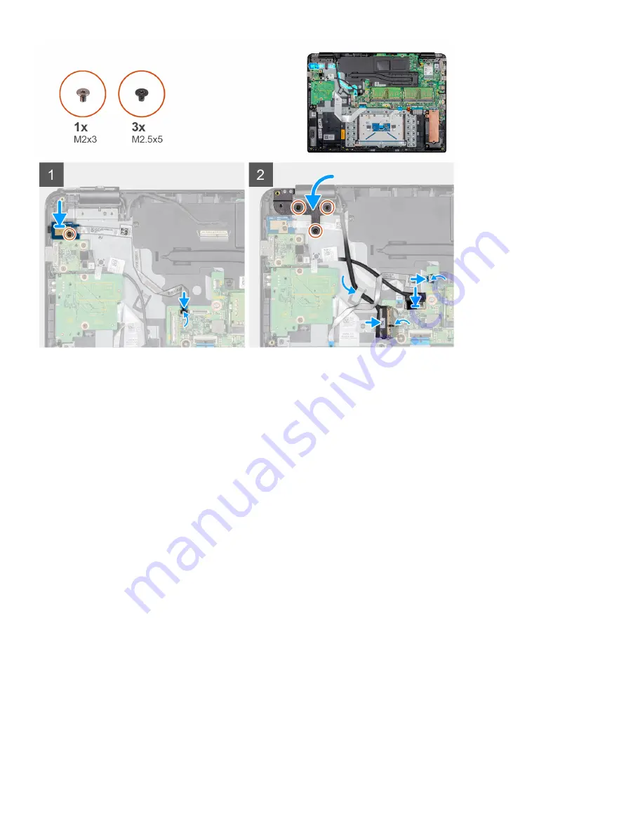
Place the power-button board into the slot on the palm-rest and keyboard assembly.

Replace the screw (M2x3) that secures the power button board to the palm-rest and keyboard assembly.

Adhere the power button cable to the palm-rest and keyboard assembly.

Slide the power button cable to the system board and close the latch to secure the cable.

Route the display cable through the routing guide.

Connect the display cable to the system board and close the latch to secure the cable.

Adhere the tape that secures the display cable to the system board.

Connect the VGA daughterboard cable to the system board and close the latch to secure the cable.

Slide the CAC reader cable to the respective port on the system board and close the latch to secure the cable.

10  Press the left hinge to the palm-rest and keyboard assembly.
11  Replace the three screws (M2.5x5) that connect the left hinge to the keyboard and palm-rest assembly.

Next steps

1

Installing the 

battery

.

2

Installing the 

base cover

.

3

Installing the 

SD memory card

.

4

Follow the procedure in 

After working on your thin client

.

Heat sink

Removing the heat sink

Prerequisites

1

Follow the procedure in 

Before working on your thin client

.

2

Removing the 

SD memory card

.

44

Removing and installing components

Содержание Wyse 5470

Страница 1: ...Dell Wyse 5470 Thin Client Service Manual ...

Страница 2: ...amage to hardware or loss of data and tells you how to avoid the problem WARNING A WARNING indicates a potential for property damage personal injury or death 2019 Dell Inc or its subsidiaries All rights reserved Dell EMC and other trademarks are trademarks of Dell Inc or its subsidiaries Other trademarks may be trademarks of their respective owners 2019 08 Rev A00 ...

Страница 3: ...gital card 11 Removing the Secure Digital card 11 Installing the Secure Digital card 12 Base cover 12 Removing the base cover 12 Installing the base cover 14 Battery 16 Lithium ion battery precautions 16 Removing the battery 16 Installing the battery 17 Memory modules 18 Removing the memory module 18 Installing the memory module 19 Solid state drive 20 Removing the M 2 solid state drive 20 Install...

Страница 4: ...alling the heat sink 45 System board 46 Removing the system board 46 Installing the system board 48 Power adapter port 50 Removing the power adapter port 50 Installing the power adapter port 51 Display bezel 52 Removing the display bezel 52 Installing the display bezel 53 Display panel 55 Removing the display panel 55 Installing the display panel 57 Camera 59 Removing the camera 59 Installing the ...

Страница 5: ...ent 72 Post behavior 73 Wireless options 74 Virtualization support screen options 74 Maintenance screen options 75 System logs 75 4 Troubleshooting your system 76 Enhanced Pre Boot System Assessment diagnostics 76 Running the ePSA diagnostics 76 Battery status LED 77 Diagnostic LED 77 Power behavior 78 5 Getting help 79 Contacting Dell 79 Contents 5 ...

Страница 6: ...ly touching an unpainted metal surface at the same time as touching a connector on the back of the thin client CAUTION Handle components and cards with care Do not touch the components or contacts on a card Hold a card by its edges or by its metal mounting bracket Hold a component such as a processor by its edges not by its pins CAUTION When you disconnect a cable pull on its connector or on its p...

Страница 7: ...ially sensitive components such as expansion cards processors memory DIMMs and system boards Very slight charges can damage circuits in ways that may not be obvious such as intermittent problems or a shortened product life span As the industry pushes for lower power requirements and increased density ESD protection is an increasing concern Due to the increased density of semiconductors used in rec...

Страница 8: ... have your own wrist strap tester check with your regional office to find out if they have one To perform the test plug the wrist strap s bonding wire into the tester while it is strapped to your wrist and push the button to test A green LED is lit if the test is successful a red LED is lit and an alarm sounds if the test fails Insulator Elements It is critical to keep ESD sensitive devices such a...

Страница 9: ...Lift with your legs not your back 4 Keep the load close The closer it is to your spine the less force it exerts on your back 5 Keep your back upright whether lifting or setting down the load Do not add the weight of your body to the load Avoid twisting your body and back 6 Follow the same techniques in reverse to set the load down After working on your thin client About this task CAUTION You must ...

Страница 10: ...plate Palm rest and keyboard assembly M2x3 1 Solid state drive Palm rest and keyboard assembly M2x2 1 Battery Palm rest and keyboard assembly M2x3 4 CAC reader Palm rest and keyboard assembly M2x3 4 WLAN card System board M2x3 1 I O board Palm rest and keyboard assembly M2X3 2 Touch pad bracket Palm rest and keyboard assembly M2x2 3 Touch pad Palm rest and keyboard assembly M2x2 4 VGA daughterboar...

Страница 11: ...y panel Display back cover and hinges M2 5x5 6 Display panel Display back cover and hinges M2x2 2 Secure Digital card Removing the Secure Digital card About this task The following image indicates the location of the Secure Digital card and provides a visual representation of the removal procedure Steps 1 Push the secure digital card to release it from the thin client 2 Slide the secure digital ca...

Страница 12: ...rovides a visual representation of the installation procedure Step Slide the secure digital into the slot until it clicks into place Base cover Removing the base cover Prerequisites 1 Follow the procedure in Before working on your thin client 2 Removing the SD memory card About this task The following images indicate the location of the base cover and provide a visual representation of the removal...

Страница 13: ...Removing and installing components 13 ...

Страница 14: ... assembly 3 Lift the base cover off the palm rest and keyboard assembly Installing the base cover Prerequisite If you are replacing a component remove the existing component before performing the installation procedure About this task The following images indicate the location of the base cover and provide a visual representation of the installation procedure 14 Removing and installing components ...

Страница 15: ...Removing and installing components 15 ...

Страница 16: ...ttery to high temperatures or disassemble battery packs and cells Do not apply pressure to the surface of the battery Do not bend the battery Do not use tools of any kind to pry on or against the battery If a battery gets stuck in a device as a result of swelling do not try to free it as puncturing bending or crushing a Lithium ion battery can be dangerous In such an instance contact https www del...

Страница 17: ...tery off the palm rest and keyboard assembly Installing the battery Prerequisite If you are replacing a component remove the existing component before performing the installation procedure About this task The following image indicates the location of the battery and provides a visual representation of the installation procedure Removing and installing components 17 ...

Страница 18: ...ase cover 2 Installing the SD memory card 3 Follow the procedure in After working on your thin client Memory modules Removing the memory module Prerequisites 1 Follow the procedure in Before working on your thin client 2 Removing the SD memory card 3 Removing the base cover 4 Removing the battery About this task The following image indicates the location of the memory module and provides a visual ...

Страница 19: ...mory module slot on the system board Installing the memory module Prerequisite If you are replacing a component remove the existing component before performing the installation procedure About this task The following image indicates the location of the memory module and provides a visual representation of the installation procedure Removing and installing components 19 ...

Страница 20: ...2 Installing the base cover 3 Installing the SD memory card 4 Follow the procedure in After working on your thin client Solid state drive Removing the M 2 solid state drive Prerequisites 1 Follow the procedure in Before working on your thin client 2 Removing the SD memory card 3 Removing the base cover 4 Removing the battery About this task The following image indicates the location of the M 2 sol...

Страница 21: ... rest and keyboard assembly 4 Slide and remove the solid state drive from the solid state drive slot Installing the M 2 solid state drive Prerequisite If you are replacing a component remove the existing component before performing the installation procedure About this task The following image indicates the location of the solid state drive and provides a visual representation of the installation ...

Страница 22: ...e on the solid state drive slot 4 Replace the screw M2x3 that secures the thermal plate to the palm rest and keyboard assembly Next steps 1 Installing the battery 2 Installing the base cover 3 Installing the SD memory card 4 Follow the procedure in After working on your thin client Speakers Removing the speakers Prerequisites 1 Follow the procedure in Before working on your thin client 2 Removing ...

Страница 23: ...e from the routing guides on the palm rest and keyboard assembly 3 Lift the speakers with the cable from the palm rest and keyboard assembly Installing the speakers Prerequisite If you are replacing a component remove the existing component before performing the installation procedure About this task The following image indicates the location of the speakers and provides a visual representation of...

Страница 24: ...ery 2 Installing the base cover 3 Installing the SD memory card 4 Follow the procedure in After working on your thin client CAC reader Removing the CAC reader Prerequisites 1 Follow the procedure in Before working on your thin client 2 Removing the SD memory card 3 Removing the base cover 4 Removing the battery About this task The following image indicates the location of the Secure Digital card a...

Страница 25: ... the CAC reader from the palm rest and keyboard assembly Installing the CAC reader Prerequisite If you are replacing a component remove the existing component before performing the installation procedure About this task The following image indicates the location of the CAC reader and provides a visual representation of the installation procedure Removing and installing components 25 ...

Страница 26: ...Next steps 1 Installing the battery 2 Installing the base cover 3 Installing the SD memory card 4 Follow the procedure in After working on your thin client WLAN card Removing the WLAN card Prerequisites 1 Follow the procedure in Before working on your thin client 2 Removing the SD memory card 3 Removing the base cover 4 Removing the battery About this task The following image indicates the locatio...

Страница 27: ...remove the WLAN card bracket that secures the antenna cables 5 Slide and remove the WLAN card from the WLAN slot Installing the WLAN card Prerequisite If you are replacing a component remove the existing component before performing the installation procedure About this task The following image indicates the location of the WLAN card and provides a visual representation of the installation procedur...

Страница 28: ...cket to the WLAN card Next steps 1 Installing the battery 2 Installing the base cover 3 Installing the SD memory card 4 Follow the procedure in After working on your thin client IO board Removing the IO board Prerequisites 1 Follow the procedure in Before working on your thin client 2 Removing the SD memory card 3 Removing the base cover 4 Removing the battery 5 Removing the CAC reader About this ...

Страница 29: ...nd keyboard assembly 4 Lift the I O board with the cable from the palm rest and keyboard assembly Installing the IO board Prerequisite If you are replacing a component remove the existing component before performing the installation procedure About this task The following image indicates the location of the I O board and provides a visual representation of the installation procedure Removing and i...

Страница 30: ...ose the latch to secure the cable Next steps 1 Installing the CAC reader 2 Installing the battery 3 Installing the base cover 4 Installing the SD memory card 5 Follow the procedure in After working on your thin client Coin cell battery Removing the coin cell battery Prerequisites 1 Follow the procedure in Before working on your thin client 2 Replacing the SD memory card 3 Replacing the base cover ...

Страница 31: ...ry out of the slot on the I O board 3 Remove the coin cell battery from the thin client Installing the coin cell battery Prerequisite If you are replacing a component remove the existing component before performing the installation procedure About this task The following image indicates the location of the coin cell battery and provides a visual representation of the installation procedure Removin...

Страница 32: ...er 5 Installing the SD memory card 6 Follow the procedure in After working on your thin client Touch pad Removing the touch pad assembly Prerequisites 1 Follow the procedure in Before working on your thin client 2 Removing the SD memory card 3 Removing the base cover 4 Removing the battery About this task The following image indicates the location of the touch pad assembly and provides a visual re...

Страница 33: ...ssembly 6 Remove the four screws M2x2 that secure the touch pad to the palm rest and keyboard assembly 7 Peel the two tapes that secure the touch pad 8 Lift the touch pad off the palm rest and keyboard assembly Installing the touch pad assembly Prerequisite If you are replacing a component remove the existing component before performing the installation procedure About this task The following imag...

Страница 34: ...ad bracket into the slot on the palm rest and keyboard assembly 7 Replace the three screws M2x2 that secure the touch pad bracket to the palm rest and keyboard assembly 8 Adhere the tape that secures the bracket to the palm rest and keyboard assembly Next steps 1 Installing the battery 2 Installing the base cover 3 Installing the SD memory card 4 Follow the procedure in After working on your thin ...

Страница 35: ...terboard cable from the system board 4 Remove the two screws M2x3 that secure the VGA daughterboard to the palm rest and keyboard assembly 5 Lift the VGA daughterboard away from the system Installing the VGA daughterboard Prerequisite If you are replacing a component remove the existing component before performing the installation procedure About this task The following image indicates the locatio...

Страница 36: ...e to the system board 6 Slide the CAC reader cable to the respective port on the system board and close the latch to secure the cable Next steps 1 Installing the battery 2 Installing the base cover 3 Installing the SD memory card 4 Follow the procedure in After working on your thin client Display assembly Removing the display assembly Prerequisites 1 Follow the procedure in Before working on your ...

Страница 37: ...About this task The following images indicate the location of the display assembly and provide a visual representation of the removal procedure Removing and installing components 37 ...

Страница 38: ...38 Removing and installing components ...

Страница 39: ...ng the wireless antenna and disconnect the antennas from the system board 7 Disconnect the display cable from the connector on the system board 8 Lift the palm rest and keyboard assembly at an angle 9 Lift the hinges to release the palm rest and keyboard assembly off the display assembly 10 Slide and remove the palm rest and keyboard assembly off the display assembly After performing all the prece...

Страница 40: ...About this task The following images indicate the location of the display assembly and provide a visual representation of the installation procedure 40 Removing and installing components ...

Страница 41: ...Removing and installing components 41 ...

Страница 42: ...e connector on the system board 7 Close the latch to secure the cable 8 Adhere the tape that secures the display cable to the system board Next steps 1 Installing the WLAN 2 Installing the battery 3 Installing the base cover 4 Installing the SD memory card 5 Follow the procedure in After working on your thin client Power button board Removing the power button board Prerequisites 1 Follow the proce...

Страница 43: ...he routing guide 8 Open the latch and disconnect the power button board cable from the system board 9 Remove the screw M2x3 that secures the power button board to the palm rest and keyboard assembly 10 Peel the power button cable off the palm rest and keyboard assembly 11 Lift the power button board with the cable from the palm rest and keyboard assembly Installing the power button board Prerequis...

Страница 44: ...y cable to the system board 8 Connect the VGA daughterboard cable to the system board and close the latch to secure the cable 9 Slide the CAC reader cable to the respective port on the system board and close the latch to secure the cable 10 Press the left hinge to the palm rest and keyboard assembly 11 Replace the three screws M2 5x5 that connect the left hinge to the keyboard and palm rest assemb...

Страница 45: ...six captive screws M2x3 that secure the heat sink to the system board 2 Carefully lift the heat sink and place it away from the system Installing the heat sink Prerequisite If you are replacing a component remove the existing component before performing the installation procedure About this task The following image indicates the location of the heat sink and provides a visual representation of the...

Страница 46: ...e SD memory card 4 Follow the procedure in After working on your thin client System board Removing the system board Prerequisites 1 Follow the procedure in Before working on your thin client 2 Removing the SD memory card 3 Removing the base cover 4 Removing the battery 5 Removing the WLAN 6 Removing the Memory 7 Removing the SSD About this task The following image indicates the location of the sys...

Страница 47: ...Removing and installing components 47 ...

Страница 48: ...rest and keyboard assembly 11 Lift the right hinge from the system board and palm rest and keyboard assembly 12 Open the latch and disconnect the power adapter cable from the system board 13 Remove the five screws three M2x3 and two M2x2 that secures the system board to the palm rest and keyboard assembly 14 Loosen the captive screw M2x3 that is marked as 6 on the heat sink 15 Lift the system boar...

Страница 49: ...Removing and installing components 49 ...

Страница 50: ...n the system board and close the latch to secure the cable 11 Connect the display cable on to the system board close the latch and adhere the tape 12 Slide the VGA daughterboard cable in to the VGA daughterboard cable port on the system board and close the latch to secure the cable 13 Slide the power button board cable in to the power button board cable port on the system board and close the latch...

Страница 51: ...Remove the screw M2x3 that secures the power adapter port to the palm rest and keyboard assembly 6 Lift the power adapter port with the cable from the palm rest and keyboard assembly Installing the power adapter port Prerequisite If you are replacing a component remove the existing component before performing the installation procedure About this task The following image indicates the location of ...

Страница 52: ...m board and palm rest and keyboard assembly Next steps 1 Installing the WLAN 2 Installing the battery 3 Installing the base cover 4 Installing the SD memory card 5 Follow the procedure in After working on your thin client Display bezel Removing the display bezel Prerequisites 1 Follow the procedure in Before working on your thin client 2 Removing the SD memory card 3 Removing the base cover 4 Remo...

Страница 53: ... and antenna assembly Installing the display bezel Prerequisite If you are replacing a component remove the existing component before performing the installation procedure About this task The following image indicates the location of the display bezel and provides a visual representation of the installation procedure Removing and installing components 53 ...

Страница 54: ...he display bezel into place Next steps 1 Installing the display assembly 2 Installing the WLAN 3 Installing the battery 4 Installing the base cover 5 Installing the SD memory card 6 Follow the procedure in After working on your thin client 54 Removing and installing components ...

Страница 55: ...the SD memory card 3 Removing the base cover 4 Removing the battery 5 Removing the WLAN 6 Removing the display assembly 7 Removing the display bezel About this task The following image indicates the location of the display panel and provides a visual representation of the removal procedure Removing and installing components 55 ...

Страница 56: ...56 Removing and installing components ...

Страница 57: ...isplay back cover NOTE Do not pull and release the Stretch SR Tapes from the display panel There is no need to separate the brackets from the display panel After performing all the preceding steps you are left with the display panel Installing the display panel Prerequisite If you are replacing a component remove the existing component before performing the installation procedure About this task T...

Страница 58: ...58 Removing and installing components ...

Страница 59: ...y back cover Next steps 1 Installing the display bezel 2 Installing the display assembly 3 Installing the WLAN 4 Installing the battery 5 Installing the base cover 6 Installing the SD memory card 7 Follow the procedure in After working on your thin client Camera Removing the camera Prerequisites 1 Follow the procedure in Before working on your thin client 2 Removing the SD memory card 3 Removing t...

Страница 60: ...dule from the display back cover Installing the camera Prerequisite If you are replacing a component remove the existing component before performing the installation procedure About this task The following image indicates the location of the camera and provides a visual representation of the installation procedure 60 Removing and installing components ...

Страница 61: ...ting channels Next steps 1 Installing the display panel 2 Installing the display bezel 3 Installing the display assembly 4 Installing the WLAN 5 Installing the battery 6 Installing the base cover 7 Installing the SD memory card 8 Follow the procedure in After working on your thin client Removing and installing components 61 ...

Страница 62: ...y 7 Removing the SSD 8 Removing the CAC reader 9 Removing the IO board 10 Removing the touch pad assembly 11 Removing the VGA daughterboard 12 Removing the speakers 13 Removing the display assembly 14 Removing the system board 15 Removing the power adapter port 16 Removing the power button board About this task The following image indicates the location of the I O board and provides a visual repre...

Страница 63: ...ep Place the palm rest and keyboard assembly on a flat surface Next steps 1 Installing the power button board 2 Installing the power adapter port 3 Installing the system board 4 Installing the display assembly 5 Installing the speakers 6 Installing the VGA daughterboard 7 Installing the touch pad assembly 8 Installing the IO board 9 Installing the CAC reader 10 Installing the SSD 11 Installing the...

Страница 64: ...user selectable option such as the user password Read the current amount of memory or set the type of hard drive installed Before you use System Setup Dell recommends that you write down the System Setup screen information for future reference CAUTION Unless you are an expert thin client user do not change the settings for this program Certain changes can cause your thin client to work incorrectly...

Страница 65: ... Service Tag Asset Tag Ownership Tag Ownership Date Manufacture Date Express Service Code the Signed Firmware update enabled by default Memory Information Displays Memory Installed Memory Available Memory Speed Memory Channels Mode Memory Technology DIMM A Size DIMM B Size NOTE Since Memory Available is less than the Memory Installed certain operating systems may not be able to use all the availab...

Страница 66: ...nfiguration Option Description Integrated NIC Allows you to configure the integrated network controller Click one of the following options Enable UEFI Network Stack If enabled UEFI networking protocols are installed allowing pre operating system and early operating system networking features to use enabled NICs This maybe used without PXE turned on Integrated NIC Disabled Enabled Enabled w PXE Def...

Страница 67: ...ttings USB PowerShare Allows you to On or Off external devices to be powered or charged using the stored system battery Audio Allows you to switch all integrated audio On Off or enable disable the microphone and the internal speaker separately The options are Enable Audio Enable Microphone Enable Internal Speaker This option is enabled by default Keyboard Illumination This field lets you choose th...

Страница 68: ...d SD Read Only Mode Secure Digital SD Card Boot Video screen options Table 5 Video Option Description LCD Brightness Allows you to set the display brightness depending upon the power source On Battery 50 is default and On AC 100 default Security screen options Table 6 Security screen options Option Description Admin Password This option enables you to set change or delete the administrator passwor...

Страница 69: ...aximum value is set to 32 You can decrease the value Password Bypass This option enables you to enable and disable the permission to bypass the system and the internal hard drive password when they are set The options are Disabled enabled by default Reboot Bypass Password Change This option enables you to enable the disable permission to the system and hard drive passwords when the administrator p...

Страница 70: ...scription Secure Boot Enable This option enables or disables the secure boot feature By default the Secure Boot Enable option is not set Secure Boot Mode This option enables you to change the secure boot operation mode modifies the behavior of secure boot to allow evaluation or enforcement of the UEFI driver signatures The options include Deployed Mode Audit Mode Expert Key Management This option ...

Страница 71: ...serve Memory size When SGX is set to Software Controlled this setting is not available and has no effect The options include 32 MB 64 MB 128 MB default Performance screen options Table 9 Performance options Option Description Multi Core Support This option specifies whether one or more cores are enabled on the processor The options include All enabled by default 1 2 3 Intel SpeedStep This option e...

Страница 72: ...wer up from the off state when triggered by a special LAN signal Wake up from the Standby state is unaffected by this setting and must be enabled in the operating system This feature only works when the thin client is connected to AC power supply Disabled Does not allow the system to power on by special LAN signals when it receives a wake up signal from the LAN or wireless LAN LAN Only Allows the ...

Страница 73: ...tion specifies if the Numlock function should be enabled when the system boots The option is set by default Fn Lock Options Allows you to let hot key combinations Fn Esc toggle the primary behavior of F1 F12 between their standard and secondary functions If you disable this option you cannot toggle dynamically the primary behavior of these keys Fn Lock Default Click one of the following options Lo...

Страница 74: ...llowing options Passthrough MAC Address Default Integrated NIC 1 MAC Address Disabled Wireless options Table 12 Wireless Option Description Wireless Switch Allows to set the wireless devices that can be controlled by the wireless switch The options are WLAN WiGig Bluetooth NOTE For WLAN and WiGig enable or disable controls are tied together and they cannot be enabled or disabled independently All ...

Страница 75: ...default Data Wipe This field enables you to erase the data securely from all internal storage devices Option Wipe on Next boot is not enabled by default The following is the list of devices affected Internal SATA HDD SSD Internal M 2 SATA SDD Internal M 2 PCIe SSD Internal eMMC CAUTION If you enable this option all the data is permanently deleted BIOS Recovery This option enables you to recover ce...

Страница 76: ...s a set of options for particular devices or device groups enabling you to Run tests automatically or in an interactive mode Repeat tests Display or save test results Run thorough tests to introduce additional test options to provide extra information about the failed devices View status messages that inform you if tests are completed successfully View error messages that inform you of problems en...

Страница 77: ...F The system is in a shutdown state Diagnostic LED This section details the diagnostic features of the battery LED Instead of beep codes errors are indicated via the bicolor Battery Charge Status LED A specific blink pattern is followed by flashing a pattern of flashes in amber followed by white The pattern then repeats NOTE The diagnostic pattern consists of a two digit number being represented b...

Страница 78: ...t full speed None AC adapter Power is less than the system power requirements at full CPU speed Lower the maximum CPU speed to a value that does not exceed the power available by the AC adapter Alert xxxxxxW AC power adapter has been detected which is less than the recommended xxxxxxW AC adapter originally shipped The system adjusts the performance to match the power available Connect a Dell xxxxx...

Страница 79: ...ne based support and service options Availability varies by country and product and some services may not be available in your area To contact Dell for sales technical support or customer service issues Steps 1 Go to Dell com support 2 Select your support category 3 Verify your country or region in the Choose a Country Region drop down list at the bottom of the page 4 Select the appropriate servic...

Отзывы: