background image

Back to Contents Page


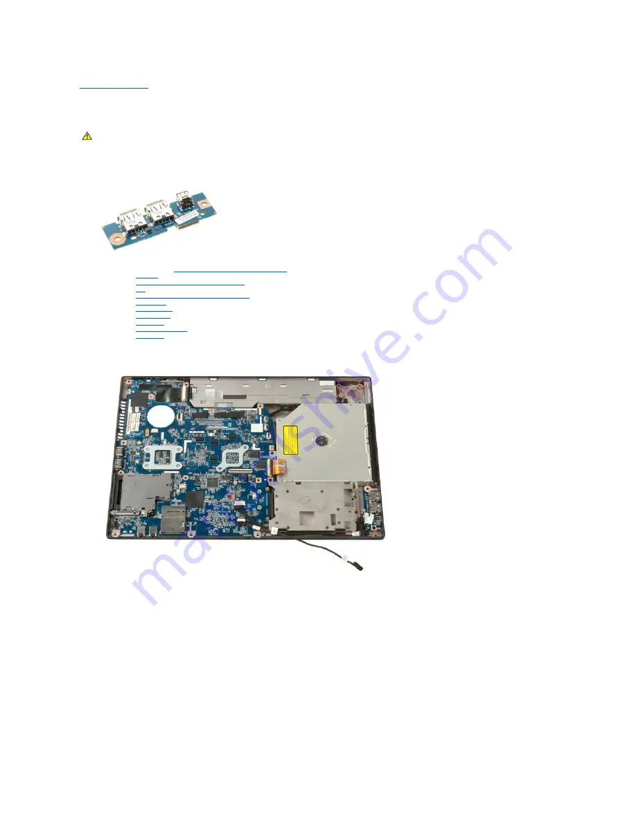
USB/IEEE 1394 Board 

Dell™ Vostro™ 1520 Service Manual


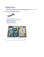
Removing the USB/IEEE 1394 Board 


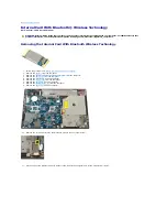
1.

Follow the procedures in 

Before Working Inside Your Computer

.  

2.

Remove the 

battery

 from the computer.  

3.

Remove the 

processor and memory access panel

 from the computer.  

4.

Remove the 

fan

 from the computer.  

5.

Remove the 

hard drive and mini-card access panel

 from the computer.  

6.

Remove the 

hard drive

 from the computer.  

7.

Remove the 

optical drive

 from the computer.  

8.

Remove the 

hinge cover

 from the computer.  

9.

Remove the 

keyboard

 from the computer.  

10.

Remove the 

display assembly

 from the computer.  

11.

Remove the 

palm rest

 from the computer.  


12.

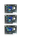
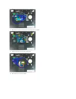
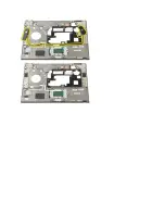
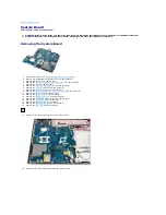
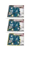
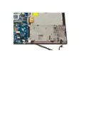
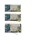
Remove the screw that secures the USB/1394 connector board to the computer chassis. 

WARNING: 

Before working inside your computer, read the safety information that shipped with your computer. For additional safety best 

practices information, see the Regulatory Compliance Homepage at www.dell.com/regulatory_compliance. 

Содержание Vostro 1520

Страница 1: ...chStrip is a trademark of Zvetco Biometrics LLC Blu ray Disc is a trademark of the Blu ray Disc Association Microsoft Windows Windows Vista and the Windows Vista start button are either trademarks or registered trademarks of Microsoft Corporation in the United States and or other countries Other trademarks and trade names may be used in this document to refer to either the entities claiming the ma...

Страница 2: ...reboot and press the F2 key when the keyboard LEDs first flash F12 Menu Press F12 when the Dell logo appears to initiate a one time boot menu with a list of the valid boot devices for the computer The devices listed on the boot menu depend on the bootable devices installed in the computer l Internal HDD l CD DVD CD RW Drive l Onboard NIC l BIOS Setup l Diagnostics starts the Pre boot System Assess...

Страница 3: ...ights located in the center of the hinge cover 1 Turns on when your computer reads or writes data to the hard drive NOTE To avoid loss of data never turn off your computer while the Hard Drive light is flashing 2 Turns on when wireless networking is enabled 3 Turns on when a card with Bluetooth wireless technology is enabled NOTE The card with Bluetooth wireless technology is an optional feature s...

Страница 4: ...module in the same slot and test Test the other slot with both modules 3 Replace the memory 4 Replace the system board ON FLASH ON Memory is detected but has errors 1 Reseat the memory 2 If two modules are installed remove one and test Try the other module in the same slot and test Test the other slot with both modules 3 Replace the memory 4 Replace the system board OFF FLASH FLASH Modem Error 1 R...

Страница 5: ... Panel Heat Sink and Processork Display Assembly Camera LCD Display Panel Keyboard USB IEEE 1394 Board Speaker Assembly Coin Cell Battery Hard Drive and Mini Card Access Panel Wireless Wide Area Network WWAN Card Internal Card With Bluetooth Wireless Technology Fan Memory Hinge Cover Display Bezel Display Assembly Hinges Display Inverter Palm Rest Fingerprint Reader System Board ...

Страница 6: ...em Information System chipset Intel GM45 or Intel PM45 chipset Data bus width 64 bits DRAM bus width 64 bits Processor address bus width 36 bits Flash EPROM SPI 32 Mbit PCI bus discrete graphics only x16 PCI Express ExpressCard optional NOTE The ExpressCard slot is designed only for ExpressCards It does NOT support PC cards ExpressCard connector ExpressCard slot USB and PCI Express based interface...

Страница 7: ...eo or PCI Express video x16 Video memory Integrated video up to 256 MB shared Discrete video 256 MB dedicated memory Video output Video connector and multimode DisplayPort Audio Audio type Two channel high definition audio codec Audio controller IDT 92HD71B5 Stereo conversion 24 Bit stereo digital to analog 24 Bit stereo analog to digital Interfaces Internal Internal High Definition Audio External...

Страница 8: ...y 84 WHr 9 cell lithium ion battery 85 WHr 6 cell lithium ion battery 56 WHr 4 cell lithium ion battery 35 WHr Dimensions Depth 4 or 6 cell lithium ion battery 206 mm 8 11 inches 9 cell lithium ion battery 93 3 mm 3 67 inches 12 cell lithium ion battery 14 48 mm 0 57 inches Height 4 or 6 cell lithium ion battery 19 8 mm 0 78 inch 9 cell lithium ion battery 22 3 mm 0 88 inch 12 cell lithium ion bat...

Страница 9: ...ght 15 mm 0 6 inches Width 66 mm 2 6 inches Depth 127 mm 5 0 inches Weight 0 29 kg 0 64 lb PA 10 90 W D Series AC adapter Output voltage 19 5 V DC Output current 4 62 A Height 32 mm 1 3 inches Width 60 mm 2 4 inches Depth 140 mm 5 5 inches Weight 0 425 kg 0 9 lb PA 3E 90 E Series AC adapter Output voltage 19 5 V DC Output current 4 62 A Height 15 mm 0 6 inches Width 70 mm 2 8 inches Depth 147 mm 5...

Страница 10: ...e 1 30 GRMS Maximum shock measured with hard drive in head parked position and a 2 ms half sine pulse Operating 143 G Storage 163 G Altitude maximum Operating 15 2 to 3048 m 50 to 10 000 ft Storage 15 2 to 3048 m 50 to 10 000 ft ...

Страница 11: ...Slide the battery lock latch on the left away from the battery 3 Slide the battery latch at the center toward the right WARNING Before working inside your computer read the safety information that shipped with your computer For additional safety best practices information see the Regulatory Compliance Homepage at www dell com regulatory_compliance ...

Страница 12: ...4 Slide the battery itself toward the back of the computer and remove ...

Страница 13: ...ve the optical drive from the computer 11 Remove the Bluetooth module from the computer 12 Remove any WLAN and WWAN cards from the computer 13 Remove the hinge cover from the computer 14 Remove the keyboard from the computer 15 Remove the display assembly from the computer 16 Remove the palm rest from the computer 17 Remove the system board from the computer 18 Set aside the chassis and place the ...

Страница 14: ......

Страница 15: ...embly from the computer 3 Remove the six rubber screw covers from the display bezel 4 Remove the six screws that secure the bezel to the display assembly WARNING Before working inside your computer read the safety information that shipped with your computer For additional safety best practices information see the Regulatory Compliance Homepage at www dell com regulatory_compliance ...

Страница 16: ...5 Remove the bezel from the display assembly ...

Страница 17: ...zel from the display assembly 4 Remove the LCD display panel from the display assembly 5 Loosen the captive screw that secures the display camera in place 6 Lift the camera from its slot WARNING Before working inside your computer read the safety information that shipped with your computer For additional safety best practices information see the Regulatory Compliance Homepage at www dell com regul...

Страница 18: ...6 Release the display camera data cable from its clip and disconnect the display camera data cable 7 Remove the display camera from the display assembly ...

Страница 19: ......

Страница 20: ...ezel from the display assembly 4 Remove the display inverter from the display assembly 5 Remove the LCD display panel from the display assembly 6 Remove the eight screws securing the hinges to the display panel assembly WARNING Before working inside your computer read the safety information that shipped with your computer For additional safety best practices information see the Regulatory Complian...

Страница 21: ...7 Slide the hinges away from the display panel assembly 8 Remove the display panel hinges from the display panel assembly ...

Страница 22: ......

Страница 23: ...play assembly from the computer 3 Remove the screw that secures the display inverter to the display assembly 4 Open the display inverter data cable clip WARNING Before working inside your computer read the safety information that shipped with your computer For additional safety best practices information see the Regulatory Compliance Homepage at www dell com regulatory_compliance ...

Страница 24: ...5 Remove the display inverter data cable from the clip 6 Disconnect the data cable from the display inverter 7 Remove the display inverter from the display assembly ...

Страница 25: ......

Страница 26: ...emove the display bezel from the display assembly 4 Remove the two screws that secure the LCD display panel to the display assembly 5 Remove the LCD display panel from the display assembly WARNING Before working inside your computer read the safety information that shipped with your computer For additional safety best practices information see the Regulatory Compliance Homepage at www dell com reg...

Страница 27: ......

Страница 28: ...inge cover from the computer 5 Remove the keyboard from the computer 6 Remove the hard drive from the computer 7 Remove the optical drive from the computer 8 Disconnect the antenna cables from the WLAN card 9 Disconnect the camera cable from the system board WARNING Before working inside your computer read the safety information that shipped with your computer For additional safety best practices ...

Страница 29: ...10 Disconnect the display data cable from the system board 11 Carefully draw the antenna cables through the system board 12 Remove the antenna cables from their routing slots ...

Страница 30: ... display data cable from its routing slot 14 Remove the four screws that secure the display assembly to the base of the computer 15 Remove the four screws that secure the display assembly to the base of the computer ...

Страница 31: ......

Страница 32: ...processor and memory access panel from the computer 4 Disconnect the fan cable from the system board 5 Remove the three screws that secure the fan to the computer WARNING Before working inside your computer read the safety information that shipped with your computer For additional safety best practices information see the Regulatory Compliance Homepage at www dell com regulatory_compliance ...

Страница 33: ...6 Lift the fan and remove it from the computer ...

Страница 34: ...r 6 Remove the hinge cover from the computer 7 Remove the keyboard from the computer 8 Remove the display assembly from the computer 9 Remove the palm rest from the computer 10 Remove the screw that secures the fingerprint reader retention plate to the computer chassis 11 Slide the fingerprint reader retention plate to the left WARNING Before working inside your computer read the safety informatio...

Страница 35: ...12 Remove the fingerprint reader retention plate 13 Open the fingerprint cable retention clip 14 Remove the fingerprint cable from the retention clip ...

Страница 36: ...15 Remove the fingerprint reader from the palm rest ...

Страница 37: ...tic scribe gently to pry the back side of the hinge cover away from the base of the computer 4 Starting on the right side separate the hinge cover from the base of the computer WARNING Before working inside your computer read the safety information that shipped with your computer For additional safety best practices information see the Regulatory Compliance Homepage at www dell com regulatory_comp...

Страница 38: ...5 Continue to separate the hinge cover from the computer working from right to left then remove the hinge cover ...

Страница 39: ...ve the hard drive and mini card access panel from the computer 4 Slide the hard drive toward the side of the computer 5 Lift and remove the hard drive from the computer WARNING Before working inside your computer read the safety information that shipped with your computer For additional safety best practices information see the Regulatory Compliance Homepage at www dell com regulatory_compliance ...

Страница 40: ......

Страница 41: ...Remove the battery from the computer 3 Remove the two screws that secure the hard drive and mini card access panel to the computer 4 Slide the panel toward the rear of the computer WARNING Before working inside your computer read the safety information that shipped with your computer For additional safety best practices information see the Regulatory Compliance Homepage at www dell com regulatory_...

Страница 42: ...5 Remove the hard drive and mini card access panel ...

Страница 43: ...from the computer 4 Remove the two screws that secure the keyboard to the computer 5 Lift the back edge of the keyboard slightly and slide the keyboard toward the back of the computer WARNING Before working inside your computer read the safety information that shipped with your computer For additional safety best practices information see the Regulatory Compliance Homepage at www dell com regulato...

Страница 44: ...6 Open the keyboard data cable clip to free the ribbon cable 7 Remove the keyboard data cable from the clip 8 Remove the keyboard from the computer ...

Страница 45: ......

Страница 46: ...connector until the memory module pops up WARNING Before working inside your computer read the safety information that shipped with your computer For additional safety best practices information see the Regulatory Compliance Homepage at www dell com regulatory_compliance NOTE DIMM A is the module closest to the system board You cannot remove DIMM A until DIMM B is removed If only 1 DIMM is install...

Страница 47: ...5 Remove the memory module from the socket ...

Страница 48: ... memory access panel from the computer 4 Remove the screw that secures the optical drive in place 5 Insert a plastic scribe into the notch and slide the optical drive slightly out of the computer WARNING Before working inside your computer read the safety information that shipped with your computer For additional safety best practices information see the Regulatory Compliance Homepage at www dell ...

Страница 49: ...6 Remove the optical drive from the computer ...

Страница 50: ... 6 Remove the keyboard from the computer 7 Remove the display assembly from the computer 8 Remove the processor and memory access panel from the computer 9 Remove the thirteen screws that secure the palm rest to the bottom of the computer 10 Turn over the computer and release the fingerprint reader data cable clip WARNING Before working inside your computer read the safety information that shipped...

Страница 51: ...11 Remove the fingerprint reader data cable from the clip 12 Release the touch pad data cable clip 13 Remove the touch pad data cable from the clip ...

Страница 52: ...14 Remove the four screws that secure the palm rest to the top of the computer 15 Disconnect the speaker cable from the system board 16 Remove the palm rest from the computer ...

Страница 53: ......

Страница 54: ...side Your Computer 2 Remove the battery from the computer 3 Loosen the two captive screws on the access panel 4 Lift the right side of the access panel WARNING Before working inside your computer read the safety information that shipped with your computer For additional safety best practices information see the Regulatory Compliance Homepage at www dell com regulatory_compliance ...

Страница 55: ...5 Remove the access panel ...

Страница 56: ...access panel from the computer 4 Remove the fan from the computer 5 Loosen the six captive screws that secure the heat sink to the system board 6 Lift the edge of the heat sink that is closest to the center of the computer WARNING Before working inside your computer read the safety information that shipped with your computer For additional safety best practices information see the Regulatory Compl...

Страница 57: ... the center of the computer then lift up the heat sink and remove it from the computer 8 Rotate the processor cam counterclockwise 9 Lift the processor straight up from its socket taking care not to bend any of the processor pins ...

Страница 58: ......

Страница 59: ... Remove the hinge cover from the computer 8 Remove the keyboard from the computer 9 Remove the display assembly from the computer 10 Remove the palm rest from the computer and place it on a clean work surface 12 Remove the four screws that secure the speaker assembly to the palm rest 13 Lift the speakers from their slots then remove the speaker assembly from the computer WARNING Before working ins...

Страница 60: ......

Страница 61: ...ccess panel from the computer 10 Remove the hard drive from the computer 11 Remove the optical drive from the computer 12 Remove the Bluetooth module from the computer 13 Remove any WLAN and WWAN cards from the computer 14 Remove the hinge cover from the computer 15 Remove the keyboard from the computer 16 Remove the display assembly from the computer 17 Remove the palm rest from the computer 18 D...

Страница 62: ...20 Remove the three screws that secure the system board to the computer chassis 21 Remove the system board from the computer chassis ...

Страница 63: ......

Страница 64: ...r 6 Remove the hard drive from the computer 7 Remove the optical drive from the computer 8 Remove the hinge cover from the computer 9 Remove the keyboard from the computer 10 Remove the display assembly from the computer 11 Remove the palm rest from the computer 12 Remove the screw that secures the USB 1394 connector board to the computer chassis WARNING Before working inside your computer read th...

Страница 65: ...13 Lift the USB 1394 connector board from its slot 14 Disconnect the data cable from the USB 1394 connector board ...

Страница 66: ...15 Lift the inside edge of the USB board and remove the board from the computer ...

Страница 67: ......

Страница 68: ...rive and mini card access panel from the computer 4 Disconnect the antenna cables from the WLAN card 5 Remove the screw that secures the WLAN card to the system board 6 Remove the WLAN card from the computer WARNING Before working inside your computer read the safety information that shipped with your computer For additional safety best practices information see the Regulatory Compliance Homepage ...

Страница 69: ......

Страница 70: ...rom the computer 6 Remove the hinge cover from the computer 7 Remove the keyboard from the computer 8 Remove the display assembly from the computer 9 Remove the palm rest from the computer 10 Remove the screw that secures the Bluetooth module to the system board 11 Lift the edge of the Bluetooth module closest to the front of the computer and lift the module from its slot WARNING Before working in...

Страница 71: ...12 Disconnect the data cable from the Bluetooth module 13 Remove the Bluetooth module from the computer ...

Страница 72: ......

Страница 73: ...rive and mini card access panel from the computer 4 Disconnect the antenna cables from the WWAN card 5 Remove the screw that secures the WWAN card to the system board 6 Remove the WWAN card from the computer WARNING Before working inside your computer read the safety information that shipped with your computer For additional safety best practices information see the Regulatory Compliance Homepage ...

Страница 74: ......
Страница 75: ... read the safety information that shipped with your computer For additional safety best practices information see the Regulatory Compliance Homepage at www dell com regulatory_compliance CAUTION Only a certified service technician should perform repairs on your computer Damage due to servicing that is not authorized by Dell is not covered by your warranty CAUTION To avoid electrostatic discharge g...

Страница 76: ...ter Working Inside Your Computer After you complete any replacement procedure ensure you connect any external devices cards and cables before turning on your computer 1 Connect any external devices such as a port replicator battery slice or media base and replace any cards such as an ExpressCard 2 Connect any telephone or network cables to your computer 3 Replace the battery 4 Connect your compute...

Отзывы: