


Back to Contents Page
Speakers
Dell™ Vostro™ 1200 Service Manual
Removing a Speaker
Replacing the Speaker
Removing a Speaker
1.
Follow the instructions in
Before You Begin
.
2.
Remove the battery (see
Removing the Battery
).
3.
Remove the hinge cover (see
Removing the Hinge Cover
).
4.
Remove the keyboard (see
Removing the Keyboard
).
5.
Remove the display assembly (see
Removing the Display Assembly
).
6.
Remove the palm rest (see
Removing the Palm Rest
).
7.
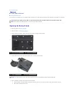
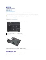
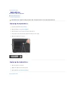
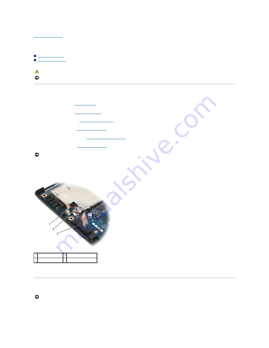
Disconnect the speaker cables for both the left and right speaker from the system board.
8.
Remove the M2.5x5-mm screws from both speakers.
9.
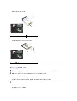
Remove the speaker cables from the routing clips and remove the speakers.
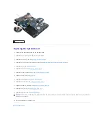
Replacing the Speaker
1.
Route the speaker cables back through the routing clips and connect the speaker cables to the system board.
CAUTION:
Before you begin the following procedure, follow the safety instructions in the
Product Information Guide
.
NOTICE:
To avoid electrostatic discharge, ground yourself by using a wrist grounding strap or by periodically touching an unpainted metal surface (such
as the back panel) on the computer.
NOTICE:
Handle the speakers with care to help prevent damaging them.
1 speaker cables (2) 2 M2.5x5-mm screws (2)
3 speakers (2)
NOTICE:
Handle the speakers with care to help prevent damaging them.
Содержание Vostro 1200
Страница 24: ...Back to Contents Page ...
Страница 35: ...Back to Contents Page ...