


7.
Remove the Media Card Reader.
8.
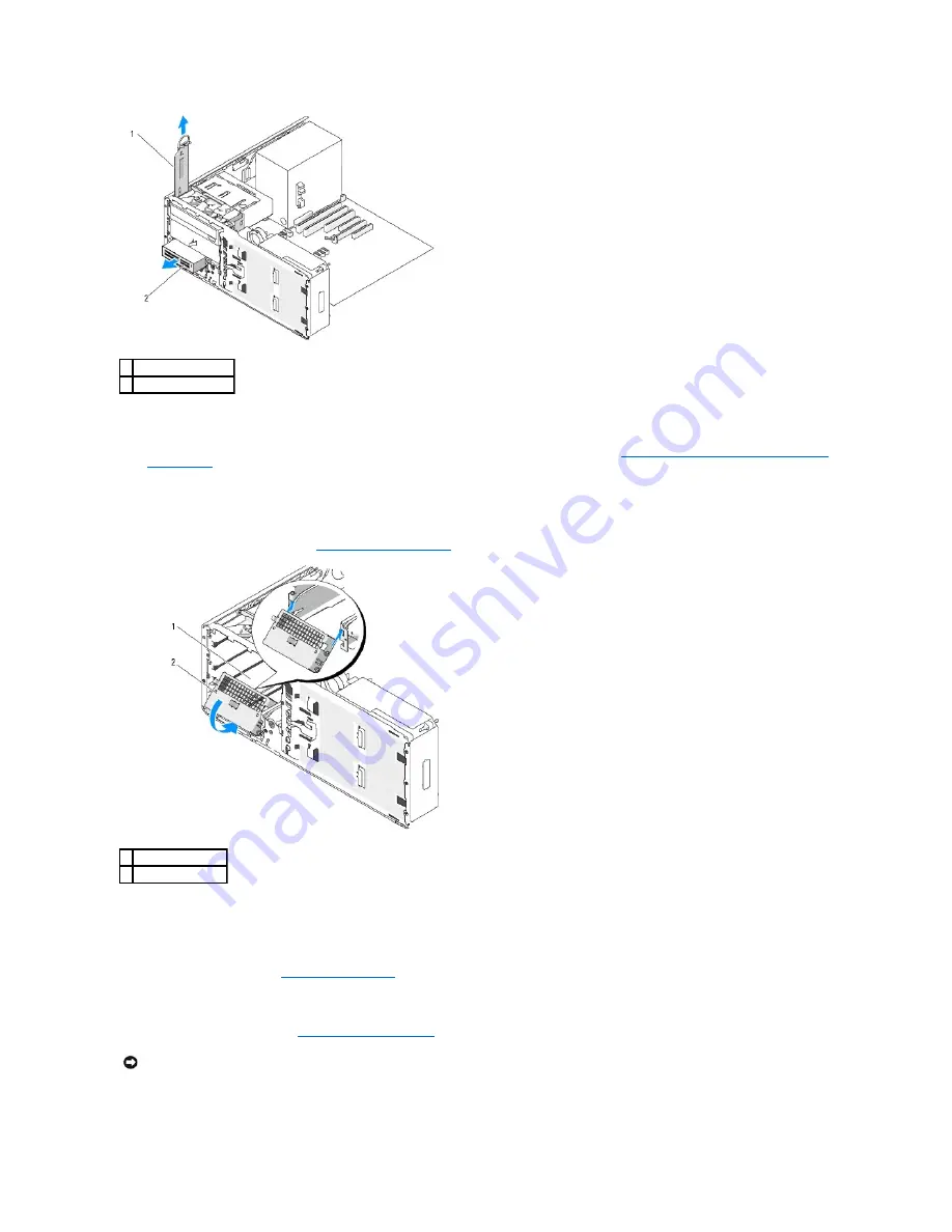
If you are not installing another drive in the FlexBay and metal shields are present in your computer (see
About the Metal Shields Present in Some Drive
Configurations
), install the vented metal insert over the FlexBay and the empty space beneath it:
a.
Holding the metal insert at an angle, insert its two upper screws into the slot that runs along the inside of the FlexBay.
b.
Rotate the bottom of the vented metal insert down and insert its two bottom screws into the slot in the open area beneath the FlexBay.
c.
Push the vented metal insert until it clicks into place and its metal tabs rest flush against the chassis surface.
Then, install a drive-panel insert (see
Replacing a Drive-Panel Insert
).
9.
If you are installing another drive in the FlexBay, see the appropriate installation instructions in this section.
10.
Replace the desktop retention insert and fold down its handle.
11.
Reinstall the drive panel (see
Replacing the Drive Panel
).
12.
Ensure that all connectors are properly cabled and firmly seated.
13.
Replace the computer cover (see
Replacing the Computer Cover
).
14.
Connect the computer and devices to electrical outlets, and turn them on.
1 drive retention insert
2 Media Card Reader
1 FlexBay
2 vented metal insert
NOTICE:
To connect a network cable, first plug the cable into the network port or device and then plug it into the computer.
Содержание Precision Workstation 490
Страница 49: ......
Страница 106: ...Back to Contents Page U S Virgin Islands General Support 1 877 673 3355 Venezuela General Support 8001 3605 ...
Страница 117: ...Back to Contents Page ...
Страница 136: ...Back to Contents Page ...


