NOTE:
The diagnostic pattern consists of a two-digit number being represented by a first group of LED blinks (1–9) in
amber, followed by a 1.5 s pause with the LED off, and then a second group of LED blinks (1–9) in white. This is then
followed by a three second pause, with the LED off, before repeating over again. Each LED blink takes 0.5 s.
The system will not shut down when displaying the Diagnostic Error Codes.
Diagnostic Error Codes always supersede any other use of the LED. For instance, on Notebooks, battery codes for Low Battery
or Battery Failure situations will not be displayed when Diagnostic Error Codes are being displayed.
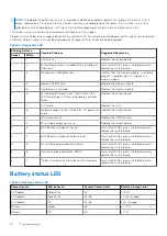
Table 3. Diagnostic LED
Blinking Pattern
Possible Problem
Suggested Resolution
Amber
White
2
1
CPU failure
Replace the system board.
2
2
System Board failure (included BIOS corruption or
ROM error)
Flash latest BIOS version. If problem persists,
replace the system board.
2
3
No Memory/ RAM detected
Confirm that the memory module.. is installed
properly. If problem persists, replace the
memory module
2
4
Memory/RAM failure
Replace the memory module.
2
5
Invalid memory installed
Replace the memory module.
2
6
System board/Chipset Error/Clock failure/Gate
A20 failure/Super I/O failure/Keyboard controller
failure
Replace the system board.
2
7
LCD failure
Replace the LCD.
2
8
No power supply to the LCD due to LCD power rail
failure
Replace the system board.
3
1
RTC power failure
Replace the CMOS battery.
3
2
PCI or Video card/chip failure
Replace the system board.
3
3
BIOS Recovery image not found
Flash latest BIOS version. If problem persists,
replace the system board.
3
4
BIOS Recovery image found but invalid
Flash latest BIOS version. If problem persists,
replace the system board.
3
5
EC ran into power sequencing failure.
Flash latest BIOS version. If problem persists,
replace the system board.
3
6
Flash corruption detected by SBIOS
Flash latest BIOS version. If problem persists,
replace the system board.
3
7
Timeout waiting on ME to reply to HECI message
Flash latest BIOS version. If problem persists,
replace the system board.
Battery status LED
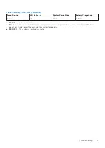
Table 4. Battery status LED
Power Source
LED behavior
System Power State
Battery Charge Level
AC Adapter
Solid White
S0
0-100%
AC Adapter
Solid White
S4/S5
< Fully Charged
AC Adapter
Off
S4/S5
Fully Charged
Battery
Amber
S0
< = 10%
Battery
Off
S0
> 10%
96
Troubleshooting
Содержание Precision 7540
Страница 1: ...Dell Precision 7540 Service Manual Regulatory Model P74F Regulatory Type P74F002 August 2021 Rev A02 ...
Страница 38: ...38 Removing and installing components ...
Страница 40: ...40 Removing and installing components ...
Страница 65: ...h Slide and remove the heat sink assembly from the system Removing and installing components 65 ...
Страница 75: ...f Connect the power connector cable to the connector on the system board Removing and installing components 75 ...

