background image

Dell Precision 7540

Service Manual

Regulatory Model: P74F
Regulatory Type: P74F002
August 2021
Rev. A02

Содержание Precision 7540

Страница 1: ...Dell Precision 7540 Service Manual Regulatory Model P74F Regulatory Type P74F002 August 2021 Rev A02 ...

Страница 2: ...tial damage to hardware or loss of data and tells you how to avoid the problem WARNING A WARNING indicates a potential for property damage personal injury or death 2016 2021 Dell Inc or its subsidiaries All rights reserved Dell EMC and other trademarks are trademarks of Dell Inc or its subsidiaries Other trademarks may be trademarks of their respective owners ...

Страница 3: ...over 17 Battery 18 Lithium ion battery precautions 18 Removing the battery 19 Installing the battery 20 Keyboard 22 Removing the keyboard 22 Installing the keyboard 25 Primary memory module 28 Removing the primary memory module 28 Installing the primary memory module 29 Secondary memory module 29 Removing the secondary memory module 29 Installing the secondary memory module 30 WWAN card 31 Removin...

Страница 4: ...card cage 57 Removing the smart card cage 57 Installing the smart card cage 58 Speaker 59 Removing the speakers 59 Installing the speakers 60 LED board 61 Removing the LED board 61 Installing the LED board 62 Heat sink 63 Removing the heat sink assembly 63 Installing the heat sink assembly 66 Graphics card 68 Removing the graphics card 68 Installing the graphics card 69 System board 70 Removing th...

Страница 5: ...1 Display bracket 92 Removing the display support bracket 92 Installing the display support bracket 93 Chapter 4 Troubleshooting 95 Enhanced Pre Boot System Assessment ePSA diagnostics 95 Running the ePSA Diagnostics 95 Diagnostic LED 95 Battery status LED 96 Chapter 5 Getting help 98 Contacting Dell 98 Contents 5 ...

Страница 6: ...rap or by periodically touching an unpainted metal surface at the same time as touching a connector on the back of the computer CAUTION Handle components and cards with care Do not touch the components or contacts on a card Hold a card by its edges or by its metal mounting bracket Hold a component such as a processor by its edges not by its pins CAUTION When you disconnect a cable pull on its conn...

Страница 7: ...m the electrical outlet before performing Step 8 CAUTION To avoid electrostatic discharge ground yourself by using a wrist grounding strap or by periodically touching an unpainted metal surface at the same time as touching a connector on the back of the computer 7 Remove any installed ExpressCards or Smart Cards from the appropriate slots After working inside your computer After you complete any r...

Страница 8: ...heater applications Content Type Real time signaling of content types between display and source devices enabling a TV to optimize picture settings based on content type Additional Color Spaces Adds support for additional color models used in digital photography and computer graphics 4K Support Enables video resolutions far beyond 1080p supporting next generation displays that will rival the Digit...

Страница 9: ...d support for new transfer types Backward USB 2 0 compatibility New connectors and cable The topics below cover some of the most commonly asked questions regarding USB 3 0 USB 3 1 Gen 1 Speed Currently there are 3 speed modes defined by the latest USB 3 0 USB 3 1 Gen 1 specification They are Super Speed Hi Speed and Full Speed The new SuperSpeed mode has a transfer rate of 4 8 Gbps While the speci...

Страница 10: ...to some products that previously weren t USB territory like external RAID storage systems Listed below are some of the available SuperSpeed USB 3 0 USB 3 1 Gen 1 products External Desktop USB 3 0 USB 3 1 Gen 1 Hard Drives Portable USB 3 0 USB 3 1 Gen 1 Hard Drives USB 3 0 USB 3 1 Gen 1 Drive Docks Adapters USB 3 0 USB 3 1 Gen 1 Flash Drives Readers USB 3 0 USB 3 1 Gen 1 Solid state Drives USB 3 0 ...

Страница 11: ... connection To use this the device and the cable have to support USB Power Delivery Just having a USB Type C connection doesn t necessarily mean they do USB Type C and USB 3 1 USB 3 1 is a new USB standard USB 3 s theoretical bandwidth is 5 Gbps while USB 3 1 s is 10 Gbps That s double the bandwidth as fast as a first generation Thunderbolt connector USB Type C isn t the same thing as USB 3 1 USB ...

Страница 12: ...derbolt USB DisplayPort and power on USB Type C on a single cable features vary between different products 2 USB Type C connector and cables which are compact and reversible 3 Supports Thunderbolt Networking varies between different products 4 Supports up to 4K displays 5 Up to 40 Gbps NOTE Data transfer speed may vary between different devices Thunderbolt Icons Figure 2 Thunderbolt Iconography Va...

Страница 13: ...rive Hard drive interposer board Coin cell battery Power connector port Palm rest Touchpad button Smart card cage Speaker LED board Heat sink Graphics card System board Display assembly Display bezel Display panel Display hinges Camera eDP cable Display bracket Recommended tools The procedures in this document require the following tools Phillips 0 screwdriver Phillips 1 screwdriver Plastic scribe...

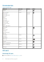
Страница 14: ... bracket M2 0x3 0 1 per SSD 1 per SSD 2 1 1 2 4 1 2 2 4 6 System board Palmrest Type C bracket LED board Power connector port GPU card M2 0x5 0 3 11 3 1 1 2 4 Cell Battery 6 Cell Battery HDD assembly M2 5x3 0 2 3 4 Display hinge M2 5x3 5 6 Hinge cap Display assembly bottom M2 5x4 0 4 2 Display assembly rear M2 5X6 0 2 HDD bracket M3 0x3 0 4 SD card Removing SD card 1 Follow the procedure in Before...

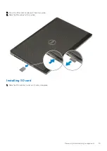
Страница 15: ...ress the SD card in to release it from the system 3 Slide the SD card out of the system Installing SD card 1 Slide the SD card into its slot until it clicks into place Removing and installing components 15 ...

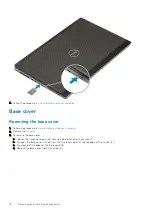
Страница 16: ... computer 2 Remove the SD card 3 To remove the base cover a Loosen the 7 captive screws that secure the base cover to the system 1 b Pry open the base cover starting from the two recess point at the top edge of the system 2 c Pry around all the edges of the base cover 3 d Remove the base cover from the system 4 16 Removing and installing components ...

Страница 17: ...se any other sharp objects as it may damage the chassis Installing the base cover 1 To install the base cover a Slide the base cover into its slot until it clicks into place 1 2 b Tighten the captive screws to secure the base cover to the system 3 Removing and installing components 17 ...

Страница 18: ...nd cells Do not apply pressure to the surface of the battery Do not bend the battery Do not use tools of any kind to pry on or against the battery Ensure any screws during the servicing of this product are not lost or misplaced to prevent accidental puncture or damage to the battery and other system components If the battery gets stuck inside your computer as a result of swelling do not try to rel...

Страница 19: ...connector on the battery 1 b Remove the 3 M2 5x3 0 screws that secure the battery to the system 2 c Remove the battery away from the system 3 4 To remove the 4 cell battery a Disconnect the battery cable from the connector on the battery 1 b Remove the 2 M2 5x3 0 screws that secure the battery to the system 2 c Remove the battery away from the system 3 Removing and installing components 19 ...

Страница 20: ...the 6 cell battery a Place the battery onto its slot in the system 1 b Replace the 3 M2 5x3 0 screws to secure the battery to the system 2 c Connect the battery cable to the connector in the battery 3 20 Removing and installing components ...

Страница 21: ...tery a Place the battery onto its slot in the system 1 b Replace the 2 M2 5x3 0 screws to secure the battery to the system 2 c Connect the battery cable to the connector in the system board 3 Removing and installing components 21 ...

Страница 22: ...keyboard 1 Follow the procedures in Before working inside your computer 2 Remove the a SD card b base cover c battery 3 To remove the keyboard a Lift the latch and disconnect the keyboard cable fingerprint cable and the fingerprint button cable from the connectors on the system board 22 Removing and installing components ...

Страница 23: ...e system at 90 angle c Using a plastic scribe pry the keyboard lattice starting from the recess points on the top edge 1 2 and work along the sides and bottom edge of the keyboard lattice Removing and installing components 23 ...

Страница 24: ... from the system e Remove the 6 M2 0x2 0 screws that secure the keyboard to the palmrest 1 f Pry the bottom edge of the keyboard and then work along the left and right sides of the keyboard 2 3 4 24 Removing and installing components ...

Страница 25: ...g Slide and remove the keyboard from the system Installing the keyboard 1 To Install the keyboard Removing and installing components 25 ...

Страница 26: ... keyboard to its compartment working along the left right and bottom edges 1 2 3 c Replace the 6 M2 0x2 0 screws to secure the keyboard to the palmrest 4 d Align the keyboard lattice to its position on the keyboard and ensure that the keyboard lattice clicks into its place 26 Removing and installing components ...

Страница 27: ...ver the system at 90 angle to access the keyboard cables f Connect the keyboard cable fingerprint cable and fingerprint button cable to the connectors on the system board 2 Removing and installing components 27 ...

Страница 28: ...side your computer 2 Remove the a SD card b base cover c battery d keyboard 3 To remove primary memory module a Remove the single M2 0x3 0 screw that secures the memory shield 1 b Slide and lift the memory shield from the memory module on the system 2 c Pry the retention clips away from the memory module until it pops up 3 d Lift the memory module and remove it from the system 4 NOTE Repeat step c...

Страница 29: ...to the memory module 4 2 Install the a keyboard b battery c base cover d SD card 3 Follow the procedure in After working inside your computer Secondary memory module Removing the secondary memory module 1 Follow the procedure in Before working inside your computer 2 Remove the a SD card b base cover c battery 3 To remove the secondary memory module a Pry the retention clips away from the memory mo...

Страница 30: ...econdary memory module 1 To install the secondary memory module a Insert the memory module into the memory socket b Press the clips to secure the memory module to the system board 30 Removing and installing components ...

Страница 31: ...he a SD card b base cover c battery 3 To remove the WWAN card a Remove the single M2 0x3 0 screw that secures the WWAN metal bracket to the system board 1 b Remove the WWAN metal bracket that secures the WWAN antenna cables 2 c Disconnect and unroute the WWAN antenna cables connected to the WWAN card 3 d Remove the WWAN card from the WWAN card slot in the system board 4 Removing and installing com...

Страница 32: ...rd 1 b Route the WWAN antenna cables through the routing channel c Connect the antenna cables to the connectors on the WWAN card 2 d Align the WWAN metal bracket above the WWAN card and replace the single M2 0x3 0 screw to secure the WWAN metal bracket to the system board 3 4 32 Removing and installing components ...

Страница 33: ...ve the a SD card b base cover c battery 3 To remove the WLAN card a Remove the single M2 0x3 0 screw that secures the WLAN metal bracket to the system board 1 b Remove the WLAN metal bracket that secures the WLAN antenna cables 2 c Disconnect and un route the antenna cables connected to the WLAN card 3 d Remove the WLAN card from the WLAN card slot in the system board 4 Removing and installing com...

Страница 34: ...rd 1 b Route the WLAN antenna cables through the routing channel c Connect the antenna cables to the connectors in the WLAN card 2 d Align the WLAN metal bracket above the WLAN card and replace the single M2 0x3 0 screw to secure the WLAN metal bracket to the system board 3 4 34 Removing and installing components ...

Страница 35: ...the a SD card b base cover c battery 3 To remove SIM card a Gently slide the SIM card cover towards the rear of the system to unlock the SIM card cover 1 CAUTION The SIM card cover is very fragile and can be easily damaged if it is not properly unlocked before opening b Filp the SIM card cover from the botton edge 2 c Lift the SIM card from the SIM card compartment 3 Removing and installing compon...

Страница 36: ...tall the SIM card a Slide the SIM card into the SIM card compartment 1 b Snap the SIM card cover down 2 c Slide the SIM card cover towards the front of the system to lock the SIM card cover 3 36 Removing and installing components ...

Страница 37: ...emove the a SD card b base cover c battery 3 To remove the M 2 SSD module Slot 4 a Remove the single M2 0x3 0 screw that secures the thermal plate to the system 1 b Slide and remove the thermal plate 2 c Remove the single M2 0x3 0 screw that secures the M 2 SSD to the system board 3 d Remove the M 2 SSD from the system 4 NOTE Repeat the above steps for removal of other M 2 SSD installed Slot 3 and...

Страница 38: ...38 Removing and installing components ...

Страница 39: ...eplace the single M2 0x3 0 screw to secure the M 2 SSD to the system board 2 c Place the thermal plate above the M 2 SSD module 3 d Replace the single M2 0x3 0 screw to secure the thermal plate to the M 2 SSD 4 NOTE Repeat the above steps to install other M 2 SSD installed Slot 3 and 5 Removing and installing components 39 ...

Страница 40: ...40 Removing and installing components ...

Страница 41: ...rocedure in Before working inside your computer 2 Remove the a SD card b base cover c battery 3 To remove hard drive assembly a Remove the 4 M2 5x3 0 screws that secure the hard drive assembly to the system 1 b Pull the tab on the hard drive assembly to disconnect the hard drive assembly from the hard drive connector 2 Removing and installing components 41 ...

Страница 42: ... the hard drive bracket e Remove the hard drive from the hard drive bracket Installing the hard drive assembly 1 To install the hard drive assembly a Place the hard drive to the hard drive bracket and replace the 4 M3 0x3 0 screws to secure the hard drive to the hard drive bracket 42 Removing and installing components ...

Страница 43: ...ve assembly to the system 2 2 Install the a base cover b SD card 3 Follow the procedure in After working inside your computer Hard drive interposer board Removing the hard drive interposer board 1 Follow the procedures in Before working inside your computer 2 Remove the a SD card Removing and installing components 43 ...

Страница 44: ...tem board 1 b Remove the hard drive interposer board from the system 2 Installing the hard drive interposer board 1 To install the hard drive interposer board a Align the hard drive interposer board into its position on the system 1 b Replace the 2 M2 0x3 0 screws to secure the hard drive interposer to the system board 2 44 Removing and installing components ...

Страница 45: ...emoving the coin cell battery 1 Follow the procedures in Before working inside your computer 2 Remove the a SD card b base cover c battery d palmrest 3 To remove coin cell battery a Disconnect the coin cell battery cable from the system 1 b Pry and lift the coin cell battery from the system 2 Removing and installing components 45 ...

Страница 46: ...within System Settings cause BitLocker or other security resets Installing the coin cell battery 1 To install the coin cell battery a Replace the coin cell battery in its slot on the system b Connect the coin cell battery cable to the system 46 Removing and installing components ...

Страница 47: ...r port 1 Follow the procedure in Before working inside your computer 2 Remove the a SD card b base cover c battery 3 To remove power connector port a Disconnect the power connector cable from the connector on the system board 1 b Peel the adhesive tape that secures the power connector cable to the system and unroute the cable 2 3 Removing and installing components 47 ...

Страница 48: ...M2 0x5 0 screw that secures the power connector cable metal bracket to the system 1 d Remove the metal bracket away from the system 2 e Lift the power connector port from the system 3 48 Removing and installing components ...

Страница 49: ...all the power connector port a Connect the power connector port to the system 1 b Place the power connector cable metal bracket 2 c Replace the single M2 0x5 0 screw to secure the metal bracket to the system 3 Removing and installing components 49 ...

Страница 50: ...ecure the power connector cable in place 1 e Route the cable through the routing channel and affix the adhesive tape 2 f Connect the power connector cable to the connector on the system board 3 50 Removing and installing components ...

Страница 51: ...e in Before working inside your computer 2 Remove the a SD card b base cover c battery d keyboard e hard drive 3 To remove the palmrest a Lift the latch and disconnect the touchpad cable from the connector on the system board 1 b Remove the 11 M2 0x5 0 and the 2 M2 0x3 0 screws that secure the palmrest assembly in place 2 3 Removing and installing components 51 ...

Страница 52: ...round and disconnect the system board cable and power button cable from the connectors on the system board 1 2 d Remove the 2 M2 0x3 0 screws that secure the palmrest to the system 3 52 Removing and installing components ...

Страница 53: ...e Push the hole at the bottom of the system to release the palmrest from the bottom chassis f Lift and remove the palmrest from the system Removing and installing components 53 ...

Страница 54: ... palmrest on the system and press until it snaps in its place b Replace the 2 M2 0x3 0 screws to secure the palmrest to the system 1 c Connect the system board and power button cable to the connectors on the system board 2 3 54 Removing and installing components ...

Страница 55: ...and replace the 2 M2 0x3 0 and the 11 M2 0x5 0 screws to secure the palmrest to the system 1 2 e Connect the touchpad cable to the connector on the system board and lock the latch 3 Removing and installing components 55 ...

Страница 56: ...w the procedure in Before working inside your computer 2 Remove the a SD card b base cover c battery d keyboard e hard drive f palmrest 3 To remove touchpad buttons a Disconnect the touchpad cable from the touchpad 1 b Remove the 2 M2 0x3 0 screws that secure the touchpad buttons to the palmrest 2 c Remove the touchpad button from the palmrest 3 56 Removing and installing components ...

Страница 57: ...chpad button cable to the connector in the touchpad 3 2 Install the a palmrest b hard drive c keyboard d battery e base cover f SD card 3 Follow the procedure in After working inside your computer Smart card cage Removing the smart card cage 1 Follow the procedure in Before working inside your computer 2 Remove the a SD card b base cover c battery d keyboard e hard drive f palmrest Removing and in...

Страница 58: ...to the palmrest 3 d Remove the smart card cage from the palmrest 4 Installing the smart card cage 1 To install the smart card cage a Place the smart card cage into its slot in the palmrest 1 b Replace the 2 M2 0X3 0 screws to secure the smart card cage to the palmrest 2 c Affix the smart card cable 3 d Connect the smart card cage cable to the connector on the palmrest 4 58 Removing and installing ...

Страница 59: ...in Before working inside your computer 2 Remove the a SD card b base cover c battery d keyboard e hard drive f palmrest 3 To remove the speaker a Disconnect the speaker cable from the system board 1 b Unroute the speaker cable and remove the cable from the routing channels c Lift the speakers along with the speaker cable and remove it away from the system 2 Removing and installing components 59 ...

Страница 60: ...the speaker a Align the speakers along the slots on the system 1 b Route the speaker cable through the routing channels on the system c Connect the speaker cable to the connector on the system board 2 60 Removing and installing components ...

Страница 61: ...he procedures in Before working inside your computer 2 Remove the a SD card b base cover c battery d keyboard e hard drive f palmrest 3 To remove LED board a Lift the tab and disconnect the LED board cable from the system board 1 b Peel the LED board cable from the system c Remove the single M2 0x5 0 screw that secures the LED board to the system 2 Removing and installing components 61 ...

Страница 62: ... LED board a Align the LED board to its original position on the system 1 b Replace the single M2 0x5 0 screw to secure the LED board to the system 2 c Affix the LED board cable d Connect the LED board cable to the connector in the system board 3 62 Removing and installing components ...

Страница 63: ... the heat sink assembly 1 Follow the procedure in Before working inside your computer 2 Remove the a SD card b base cover c battery d keyboard e hard drive f palmrest 3 To remove heat sink a Remove the 2 M2 0x3 0 screw that secures the eDP cable bracket to the system board 1 b Remove the eDP cable bracket from the system 2 Removing and installing components 63 ...

Страница 64: ...e Disconnect the two fan cables from the connector on the system board 4 5 f Loosen the 4 captive screws that secure the heat sink assembly to the system board 1 NOTE Remove the captive screws in the order stamped onto the heat sink next to the screws 1 2 3 4 g Lift the heat sink assembly 2 64 Removing and installing components ...

Страница 65: ...h Slide and remove the heat sink assembly from the system Removing and installing components 65 ...

Страница 66: ...ert the heat sink assembly in its slot on the system 1 b Tighten the 4 captive screws to secure the heat sink assembly to the system board 2 NOTE Tighten the captive screws in the order stamped onto the heat sink next to the screws 1 2 3 4 66 Removing and installing components ...

Страница 67: ...e to secure the eDP cable in place e Connect the eDP cable to the connector on the system board 3 f Place and align the eDP cable bracket above the display cable connector 4 g Replace the 2 M2 0x3 0 screw to secure the eDP cable bracket to the system board 5 Removing and installing components 67 ...

Страница 68: ...hics card 1 Follow the procedure in Before working inside your computer 2 Remove the a SD card b base cover c battery d keyboard e hard drive f palmrest g heatsink assembly 3 To remove the graphics card a Remove the 2 M2 0x3 0 screws that secure the beam connector to the system board 1 b Remove the beam connector from the system board 2 68 Removing and installing components ...

Страница 69: ...with either a 128 MB or 256 MB VRAM GPU card you need to disconnect the GPU power cable before removing the GPU card Installing the graphics card 1 To Install the graphics card a Slide the graphics card into its original position in the system 1 b Replace the 2 M2 0x5 0 screws to secure the graphics card to the system board 2 c Replace the beam connector 3 d Replace the 2 M2 0x3 0 screws to secure...

Страница 70: ...wer cable after installing the GPU card Install the a heat sink assembly b palmrest c hard drive d keyboard e battery f base cover g SD card 3 Follow the procedure in After working inside your computer System board Removing the system board 1 Follow the procedure in Before working inside your computer 2 Remove the a SD card b base cover c battery d hard drive e hard drive interposer board 70 Remov...

Страница 71: ... the power connector cable from the connector on the system board b Remove the 3 M2 0x5 0 screws that secure the Type C USB bracket to the system 1 c Remove the Type C USB bracket from the system 2 d Disconnect the touchpad cable LED board cable and speaker from the connectors on the system board 3 4 5 and peel the coin cell battery from the system 6 Removing and installing components 71 ...

Страница 72: ...re the system board in place 1 f Slide the system board to release the IO connectors from the opening on the top and left side of the system chassis to remove the system board from the system chassis 3 2 72 Removing and installing components ...

Страница 73: ...stem board 1 To install the system board a Align the system board into its original position on the system 1 2 b Replace the 3 M2 0x5 0 screws to secure the system board in place 3 Removing and installing components 73 ...

Страница 74: ... connectors on the system board 4 3 2 and affix the coin cell battery to the system 1 d Place the Type C USB bracket onto its slot on the system 5 e Replace the 3 M2 0x5 0 screws to secure the Type C USB bracket to the system 6 74 Removing and installing components ...

Страница 75: ...f Connect the power connector cable to the connector on the system board Removing and installing components 75 ...

Страница 76: ...ssembly Removing the display assembly 1 Follow the procedure in Before working inside your computer 2 Remove the a SD card b base cover c battery d keyboard e hard drive f WWAN card g WLAN card h palmrest 3 To remove display assembly a Remove the 2 M2 5x4 0 screws at the bottom of the system that secures the display assembly in place 1 b Unroute all the wireless antenna cables from the routing cha...

Страница 77: ...c Remove the 2 M2 5x6 0 screws at the rear of the system that secures the display assembly in place Removing and installing components 77 ...

Страница 78: ...he 2 M2 0x3 0 screws that secure the eDP cable bracket to the system board 1 h Remove the eDP cable bracket 2 i Disconnect the eDP cable from the connector on the system board 3 j Peel the adhesive tape that secures the eDP cable in place 4 k Unroute the wireless cable from the routing channels located next to the hinges 5 l Remove the display assembly 6 78 Removing and installing components ...

Страница 79: ... the wireless cable located next to the hinges 2 c Affix the adhesive tape to secure the eDP cable in place 3 d Connect the eDP cable to the connector on the system board 4 e Place the eDP cable bracket and replace the 2 M2 0x3 0 screws to secure the eDP cable bracket to the system board 5 6 Removing and installing components 79 ...

Страница 80: ...ce the 4 M2 5x4 0 screws to secure the display hinge caps to the system 1 2 g Close the display assembly and replace the 2 M2 5x6 0 screws at the rear of the system to secure the display assembly in place 80 Removing and installing components ...

Страница 81: ...wireless antenna cables to the routing channels at the bottom of the system 1 i Replace the 2 M2 5x4 0 screws at the bottom of the system to secure the display assembly in place 2 Removing and installing components 81 ...

Страница 82: ... inside your computer Display bezel Removing the display bezel 1 Follow the procedure in Before working inside your computer NOTE If a touch LCD is installed then the following procedure is not applicable as it is for a full hinge assembly 2 Remove the a SD card b base cover c battery d keyboard e hard drive 82 Removing and installing components ...

Страница 83: ...e of the display bezel using your hands using a screw driver or other sharp objects may damage the display cover NOTE The display bezel shipped with a non touch display is a disposable part and should be replaced with a new display bezel anytime it is removed from the system Installing the display bezel 1 To install the display bezel a Place the display bezel on the display assembly b Press the ed...

Страница 84: ... in After working inside your computer Display panel Removing the display panel 1 Follow the procedure in Before working inside your computer 2 Remove the a SD card b battery c keyboard d hard drive e WWAN card f WLAN card g palmrest h display assembly i display bezel 3 To remove screws from the display panel 84 Removing and installing components ...

Страница 85: ... the eDP cable c Lift the metal tab and disconnect the eDP cable from the connector on the display panel 5 Remove the display panel Installing the display panel 1 To install the display panel a Connect the eDP cable to the connector on the back of the display panel and affix the adhesive tape 1 2 3 4 5 b Align the display panel with the tabs on the display assembly c Replace the 4 M2 0X3 screws to...

Страница 86: ...i base cover j SD card 3 Follow the procedure in After working inside your computer Display hinges Removing the display hinge 1 Follow the procedure in Before working inside your computer 2 Remove the a SD card b base cover c battery d keyboard e hard drive f WWAN card g WLAN card 86 Removing and installing components ...

Страница 87: ...secure the display hinges to the display assembly 1 b Remove the display hinges 2 Installing the display hinge 1 To install display hinge a Place the display hinge in its slot on the display assembly 1 b Replace the 6 M2 5x3 5 screws to secure the display hinge to the display assembly 2 Removing and installing components 87 ...

Страница 88: ...i battery j base cover k SD card 3 Follow the procedure in After working inside your computer Camera Removing the camera 1 Follow the procedure in Before working inside your computer 2 Remove the a SD card b base cover c battery d keyboard e hard drive f WWAN card g WLAN card h palmrest 88 Removing and installing components ...

Страница 89: ...nnect the eDP cable from the camera module 2 c Carefully pry the camera module from the system 3 Installing the camera 1 To install the camera a Place the camera module in its slot on the system 1 b Connect the eDP cable to the camera module 2 c Affix the adhesive tape to cover the camera module 3 Removing and installing components 89 ...

Страница 90: ...rd i battery j base cover k SD card 3 Follow the procedure in After working inside your computer eDP cable Removing the eDP cable 1 Follow the procedure in Before working inside your computer 2 Remove the a SD card b base cover c battery d keyboard e hard drive f WWAN card g WLAN card 90 Removing and installing components ...

Страница 91: ...c Peel the eDP cable from the display cover and unroute the cable from the routing channels 3 d Remove the eDP cable from the system Installing the eDP cable 1 To install eDP cable a Route and affix the eDP cable on the display cover 3 b Connect the eDP cable to the connector on the camera module 2 c Affix the adhesive tape covering the camera module 1 Removing and installing components 91 ...

Страница 92: ...cover j battery k SD card 3 Follow the procedure in After working inside your computer Display bracket Removing the display support bracket 1 Follow the procedure in Before working inside your computer 2 Remove the a SD card b base cover c battery d keyboard e hard drive f WWAN card g WLAN card 92 Removing and installing components ...

Страница 93: ...port brackets to the display cover 2 c Remove the display support brackets from the display cover 3 Installing the display support bracket 1 To install the display support bracket a Place the display brackets onto its slot on the display cover 1 b Replace the 6 M2 0x3 0 screws to secure the display bracket to the display cover 2 c Affix the adhesive tape to cover the display support bracket 3 Remo...

Страница 94: ...play panel c display bezel d display assembly e palmrest f WWAN card g WLAN card h hard drive i keyboard j battery k base cover l SD card 3 Follow the procedure in After working inside your computer 94 Removing and installing components ...

Страница 95: ...ter terminal when the diagnostic tests are performed Running the ePSA Diagnostics Invoke diagnostics boot by either of the methods that are suggested below 1 Power on the computer 2 As the computer boots press the F12 key when the Dell logo is displayed 3 In the boot menu screen use Up Down arrow key to select the Diagnostics option and then press Enter NOTE The Enhanced Pre boot System Assessment...

Страница 96: ... module 2 5 Invalid memory installed Replace the memory module 2 6 System board Chipset Error Clock failure Gate A20 failure Super I O failure Keyboard controller failure Replace the system board 2 7 LCD failure Replace the LCD 2 8 No power supply to the LCD due to LCD power rail failure Replace the system board 3 1 RTC power failure Replace the CMOS battery 3 2 PCI or Video card chip failure Repl...

Страница 97: ...e Level Battery Off S4 S5 0 100 S0 ON System is turned on S4 The system consumes the least power compared to all other sleep states The system is almost at an OFF state expect for a trickle power The context data is written to hard drive S5 OFF The system is in a shutdown state Troubleshooting 97 ...

Страница 98: ...ne based support and service options Availability varies by country and product and some services may not be available in your area To contact Dell for sales technical support or customer service issues 1 Go to Dell com support 2 Select your support category 3 Verify your country or region in the Choose a Country Region drop down list at the bottom of the page 4 Select the appropriate service or s...

Отзывы: