background image

7.

Close the clamp.

8.

Install the NDC riser.

9.

If applicable, reinstall the left expansion card riser.

10. Close the system.
11. Reconnect the system to its electrical outlet and turn the system on, including any attached peripherals.

RAID Battery

Removing a RAID Battery

CAUTION: Many repairs may only be done by a certified service technician. You should only perform 

troubleshooting and simple repairs as authorized in your product documentation, or as directed by the online or 

telephone service and support team. Damage due to servicing that is not authorized by Dell is not covered by your 

warranty. Read and follow the safety instructions that came with the product.

1.

Turn off the system, including any attached peripherals, and disconnect the system from the electrical outlet.

2.

Open the system.

3.

Remove the storage controller card.
The RAID battery is located on the storage controller card.

4.

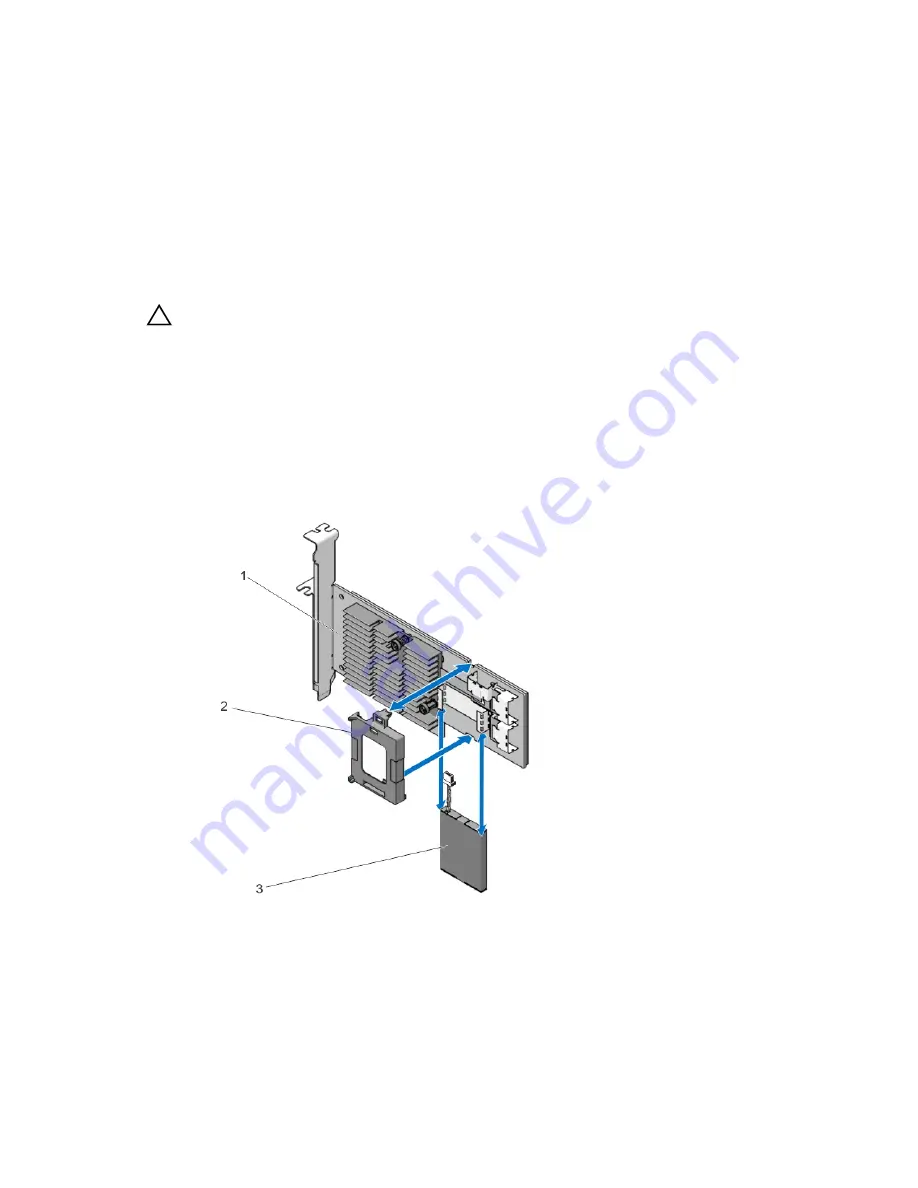
Pull the battery carrier tab from the slot and lift the RAID battery module from the storage controller card.

5.

Disconnect the battery cable from the switch on the controller card.

Figure 41. Removing and Installing the RAID Battery

1.

storage controller card

2.

battery carrier

3.

RAID battery

82

Содержание PowerEdge R920

Страница 1: ...Dell PowerEdge R920 System Owner s Manual Regulatory Model E23S Series Regulatory Type E23S001 ...

Страница 2: ...problem WARNING A WARNING indicates a potential for property damage personal injury or death Copyright 2014 Dell Inc All rights reserved This product is protected by U S and international copyright and intellectual property laws Dell and the Dell logo are trademarks of Dell Inc in the United States and or other jurisdictions All other marks and names mentioned herein may be trademarks of their res...

Страница 3: ...ing The System Setup Navigation Keys 20 System Setup Options 21 System Setup Main Screen 21 System BIOS Screen 21 System Information Screen 21 Memory Settings Screen 22 Processor Settings Screen 22 SATA Settings Screen 23 Boot Settings Screen 24 Integrated Devices Screen 24 Serial Communications Screen 25 System Profile Settings Screen 26 System Security Screen 27 Miscellaneous Settings 28 System ...

Страница 4: ...7 Cable Management Tray 38 Removing The Cable Management Tray 38 Installing The Cable Management Tray 39 System Memory 39 General Memory Module Installation Guidelines 43 Mode Specific Guidelines 43 Advanced ECC Lockstep 43 Memory Optimized Independent Channel Mode 44 Memory Sparing 44 Memory Mirroring 44 Fault Resilient Memory 44 Sample Memory Configurations 44 Removing A Memory Riser Blank 47 In...

Страница 5: ...d Riser Blank 67 Removing The Right Expansion Card Riser Blank 68 Removing An Expansion Card From Expansion Card Risers 2 and 3 68 Installing An Expansion Card Into The Expansion Card Riser 2 and 3 73 NDC Riser I O Riser 1 73 Removing The NDC Riser I O Riser 1 73 Installing The NDC Riser I O Riser 1 74 Network Daughter Card 75 Removing The Network Daughter Card 75 Installing The Network Daughter C...

Страница 6: ...Supply Bay 98 Removing The Power Distribution Board 98 Installing The Power Distribution Board 99 System Battery 99 Replacing The System Battery 99 Hard Drive Backplane 100 Removing The Hard Drive Backplane 101 Installing The Hard Drive Backplane 110 SAS Expander Daughter Card 110 Removing The SAS Expander Daughter Card 110 Installing The SAS Expander Daughter Card 111 Control Panel Board 111 Remo...

Страница 7: ...ing Expansion Cards 124 Troubleshooting Processors 124 5 Using System Diagnostics 126 Dell Embedded System Diagnostics 126 When To Use The Embedded System Diagnostics 126 Running The Embedded System Diagnostics 126 System Diagnostic Controls 126 6 Jumpers And Connectors 128 System Board Jumper Settings 128 System Board Connectors 129 Disabling A Forgotten Password 132 7 Technical Specifications 13...

Страница 8: ...Documentation feedback 157 ...

Страница 9: ...ful shutdown before power to the system is turned off 2 NMI button Used to troubleshoot software and device driver errors when running certain operating systems This button can be pressed using the end of a paper clip Use this button only if directed to do so by qualified support personnel or by the operating system documentation 3 System identification button The identification buttons on the fro...

Страница 10: ...s you to record system information such as Service Tag NIC MAC address and so on as per your need 9 Hard drives number of drives will be either 4 or 24 depending on the backplane configurations 2 5 inch hard drives NOTE On the backplane supported Flash devices there are 3 bays in total The first two bays are for PCIe Flash devices with two sets of drives labelled 0 through 3 The bay 3 is for SAS d...

Страница 11: ...re are no status messages or errors When the system is in standby mode the LCD backlight turns off after five minutes of inactivity if there are no error messages Press one of the three navigation buttons Select Left or Right to view the Home screen To navigate to the Home screen from another menu continue to select the up arrow until the Home icon is displayed and then select the Home icon From t...

Страница 12: ...esses for the iDRAC7 Addresses include DNS Primary and Secondary Gateway IP and Subnet IPv6 does not have Subnet MAC Displays the MAC addresses for iDRAC iSCSI or Network devices Name Displays the name of the Host Model or User String for the system Number Displays the Asset tag or the Service tag for the system Power Displays the power output of the system in BTU hr or Watts The display format ca...

Страница 13: ...green slowly Drive rebuilding Steady green Drive online Blinks green three seconds amber three seconds and off six seconds Rebuild aborted PCIe SSD LED Indicators Figure 4 PCIe SSD LED Indicators 1 activity indicator 2 status indicator While the operating system is running the status indicator provides the current status of the device The following table lists the device states along with the asso...

Страница 14: ...Panel Features and Indicators Item Indicator Button or Connector Icon Description 1 Power supply PSU 3 and 4 AC 750 W 1100 W or 1600 W when available or DC 1100 W 2 System identification button The identification buttons on the front and back panels can be used to locate a particular system within a rack Press to toggle the system ID on and off If the system stops responding during POST press and ...

Страница 15: ...IC connectors or Four integrated connectors that include Two 10 100 1000 Mbps NIC connectors Two 100 Mbps 1 Gbps 10 Gbps SFP 10 GbE T connectors 8 iDRAC Enterprise port Dedicated management port NOTE The port is available for use only if the iDRAC7 Enterprise license is installed on your system 9 Video connector Allows you to connect a VGA display to the system 10 Power supply PSU 1 and 2 AC 750 W...

Страница 16: ...s maximum port speed Activity indicator is blinking green Network data is being sent or received Power Indicator Codes Each AC power supply has an illuminated translucent handle and each DC power supply when available has an LED that serves as an indicator to show whether power is present or whether a power fault has occurred Figure 7 AC Power Supply Status Indicator 1 AC power supply status indic...

Страница 17: ...us and supported voltage Replace the power supply that has the flashing indicator with a power supply that matches the capacity of the other installed power supply Related Documentation WARNING See the safety and regulatory information that shipped with your system Warranty information may be included within this document or as a separate document NOTE For all PowerEdge documentation go to dell co...

Страница 18: ... for updates on dell com support manuals and read the updates first because they often supersede information in other documents Quick Resource Locator Use the Quick Resource Locator QRL to get immediate access to system information and how to videos This can be done by visiting dell com QRL or by using your smartphone and a model specific QR code located on your Dell PowerEdge system To try out th...

Страница 19: ...n the system s boot configuration F12 Starts Preboot Execution Environment PXE boot From the System Setup you can Change the NVRAM settings after you add or remove hardware View the system hardware configuration Enable or disable integrated devices Set performance and power management thresholds Manage system security You can access the System Setup using the Standard graphical browser which is en...

Страница 20: ...e the following message F2 System Setup If your operating system begins to load before you press F2 allow the system to finish booting and then restart your system and try again Responding To Error Messages If an error message is displayed while the system is booting make a note of the message For more information see System Error Messages NOTE After installing a memory upgrade it is normal for yo...

Страница 21: ... the processor such as speed cache size and so on SATA Settings Displays options to enable or disable the integrated SATA controller and ports Boot Settings Displays options to specify the boot mode BIOS or UEFI Enables you to modify UEFI and BIOS boot settings Integrated Devices Displays options to enable or disable integrated device controllers and ports and to specify related features and optio...

Страница 22: ...dvanced ECC Mode By default the Memory Operating Mode option is set to Optimizer Mode NOTE The Memory Operating Mode can have different defaults and available options based on the memory configuration Node Interleaving If this field is Enabled memory interleaving is supported if a symmetric memory configuration is installed If Disabled the system supports Non Uniform Memory architecture NUMA asymm...

Страница 23: ... in order to reduce power consumption By default the option is set to Disabled Number of Cores per Processor Allows you to control the number of enabled cores in each processor By default the Number of Cores per Processor option is set to All Processor 64 bit Support Specifies if the processor s support 64 bit extensions Processor Core Speed Displays the maximum core frequency of the processor Pro...

Страница 24: ...oot protocol is set to IPv4 NOTE This option is enabled only if the boot mode is UEFI One Time Boot Allows you to enable or disable a one time boot from a selected device Integrated Devices Screen Menu Item Description Integrated RAID Controller Allows you to enable or disable the integrated RAID controller By default the Integrated RAID Controller option is set to Enabled User Accessible USB Port...

Страница 25: ...the slot is disabled both the Option ROM and UEFI driver are disabled Serial Communications Screen Menu Item Description Serial Communication Allows you to select serial communication devices Serial Device 1 and Serial Device 2 in the BIOS BIOS console redirection can also be enabled and the port address can be specified By default Serial Communication option is set to On without Console Redirecti...

Страница 26: ...enable or disable the processor to switch to a minimum performance state when it is idle By default the C1E option is set to Enabled C States Allows you to enable or disable the processor to operate in all available power states By default the C States option is set to Enabled Monitor Mwait Allows you to enable Monitor Mwait instructions in the processor By default the Monitor Mwait option is set ...

Страница 27: ...f the TPM By default the TPM Activation option is set to No Change TPM Status Displays the TPM status TPM Clear CAUTION Clearing the TPM results in loss of all keys in the TPM The loss of TPM keys may affect booting to the operating system Allows you to clear all the contents of the TPM By default the TPM Clear option is set to No Intel TXT Allows you enable or disable Intel Trusted Execution Tech...

Страница 28: ...ust be set to enabled For more information on the password jumper settings see System Board Jumper Settings System password This is the password that you must enter before you can boot your system Setup password This is the password that you must enter to access and make changes to the BIOS or UEFI settings of your system CAUTION The password features provide a basic level of security for the data...

Страница 29: ...he system reboots Deleting Or Changing An Existing System And Or Setup Password Ensure that the Password jumper is set to enabled and the Password Status is Unlocked before attempting to delete or change the existing System and or Setup password You cannot delete or change an existing System or Setup password if the Password Status is Locked To delete or change the existing System and or Setup pas...

Страница 30: ...rd in three attempts the system displays the message Invalid Password Number of unsuccessful password attempts x System Halted Must power down Even after you shut down and restart the system the error message is displayed until the correct password is entered The following options are exceptions If System Password is not Enabled and is not locked through the Password Status option you can assign a...

Страница 31: ...ails the system continues with the next item in the boot order until the boot is successful or no more boot options are found BIOS Boot Menu Displays the list of available BIOS boot options marked with asterisks Select the boot option you wish to use and press Enter UEFI Boot Menu Displays the list of available UEFI boot options marked with asterisks Select the boot option you wish to use and pres...

Страница 32: ...nd configure the iDRAC parameters using UEFI You can enable or disable various iDRAC parameters using the iDRAC Settings Utility NOTE Accessing some of the features on the iDRAC Settings Utility requires the iDRAC7 Enterprise License upgrade For more information on using iDRAC see the iDRAC7 User s Guide at dell com esmmanuals Entering The iDRAC Settings Utility 1 Turn on or restart the managed sy...

Страница 33: ...U when available AMP 90871 1 hand crimping tool or equivalent Wire stripper pliers capable of removing insulation from size 10 AWG solid or stranded insulated copper wire NOTE Use alpha wire part number 3080 or equivalent 65 30 stranding Front Bezel Optional Removing The Front Bezel 1 Unlock the keylock at the left end of the bezel 2 Lift the release latch adjacent to the keylock 3 Rotate the left...

Страница 34: ...by yourself WARNING Opening or removing the system cover when the system is on may expose you to a risk of electric shock CAUTION Many repairs may only be done by a certified service technician You should only perform troubleshooting and simple repairs as authorized in your product documentation or as directed by the online or telephone service and support team Damage due to servicing that is not ...

Страница 35: ...m the system Figure 10 Opening and Closing the System 1 system cover 2 latch and release lock Closing The System 1 Lift the latch on the cover 2 Place the cover onto the chassis and offset the cover slightly back so that it clears the chassis hooks and lays flush on the chassis 3 Slide the cover toward the front of the system so that the chassis hooks on the back edge of the system fit the corresp...

Страница 36: ...low the safety instructions that came with the product NOTE Components that are hot swappable are marked orange and touch points on the components are marked blue Figure 11 Inside the System 1 control panel board 2 SAS expander daughter card secondary 3 hard drive backplane 4 memory riser 8 5 cooling fan 6 6 cable management tray 7 memory riser and fan cage 8 NDC 9 left power supply bay 10 left ex...

Страница 37: ...Removing And Installing The Chassis Intrusion Switch Cable 1 Turn off the system including any attached peripherals and disconnect the system from the electrical outlet 2 Open the system 3 Locate the intrusion switch on the Network Daughter Card NDC riser or riser 1 NOTE The chassis intrusion switch is detachable from the NDC riser Ensure that it is not removed so that the chassis intrusions are d...

Страница 38: ...to the processors and the expansion cards on risers when the risers are installed Removing The Cable Management Tray 1 Turn off the system including any attached peripherals and disconnect the system from the electrical outlet 2 Open the system 3 Remove the memory risers See Removing a Memory Riser 4 Remove the cooling fans See Removing A Cooling Fan 5 Remove the memory riser and fan cage See Remo...

Страница 39: ...se tab 5 Route the required cables through the cable tray 6 Close the cable tray cover 7 Install the memory riser and fan cage See Installing the Memory Riser and Fan cage 8 Install the cooling fans See Installing A Cooling Fan 9 Install the memory risers See Installing a Memory Riser 10 Close the system 11 Reconnect the system to the electrical outlet and turn the system on including any attached...

Страница 40: ...et green Two Scalable Memory Interconnect 2 SMI 2 ports that help DIMMs to connect with the processor Two Scalable Memory Buffers SMB that provide access to the DIMMs SMI 2 ports operate in two modes NOTE GT s indicates memory bus speed in Giga transfers per second Performance Mode 2 1 up to 2 66 GT s for higher bandwidth Lock Step Mode 1 1 up to 1 33 GT s for higher DDR3 speeds and better RAS Rel...

Страница 41: ...1 B5 and B9 channel 1 slots B2 B6 and B10 channel 2 slots B3 B7 and B11 channel 3 slots B4 B8 and B12 Processor 2 channel 0 slots C1 C5 and C9 channel 1 slots C2 C6 and C10 channel 2 slots C3 B7 and C11 channel 3 slots C4 C8 and C12 channel 0 slots D1 D5 and D9 channel 1 slots D2 D6 and D10 channel 2 slots D3 D7 and D11 channel 3 slots D4 D8 and D12 Processor 3 channel 0 slots E1 E5 and E9 channel...

Страница 42: ... DPC DIMM Size Operating Frequency in MT s Maximum DIMM Rank Channel DDR3 1 5 V DDR3 1 35 V RDIMM 1 4 GB 1333 and 1066 1333 and 1066 Quad rank 2 8 GB 1333 1066 Dual rank 3 16 GB 1066 Not Applicable Dual rank LRDIMM 1 32 GB 64 GB 1333 and 1066 1333 Quad rank physical 2 32 GB 64 GB 1333 and 1066 1333 Quad rank physical 3 32 GB 64 GB 1333 and 1066 Not Applicable Quad rank physical The following table...

Страница 43: ...ers then black and then green For example if you want to mix quad rank and dual rank LRDIMMs populate quad rank LRDIMMs in the sockets with white release tabs and dual rank LRDIMMs in the sockets with black release tabs The memory configuration for each processor should be identical For example if you populate socket A1 and B1 for processor 1 then populate socket C1 and D1 for processor 2 and so o...

Страница 44: ...multi bit failure protection In a mirrored configuration the total available system memory is one half of the total installed physical memory Half of the installed memory is used to mirror the active DIMMs In the event of an uncorrectable error the system will switch over to the mirrored copy This ensures SDDC and multi bit protection Memory installation guidelines Memory modules must be identical...

Страница 45: ... X X 48 4 12 X X X X X X 64 4 16 X X X X X X X X 64 8 8 X X X X 96 8 12 X X X X X X 128 8 16 X X X X X X X X 192 8 24 X X X X X X X X X X X X 64 16 4 X X X X 96 16 6 X X X X X X 128 16 8 X X X X X X X X 128 32 4 X X X X 192 32 6 X X X X X X 256 32 8 X X X X X X X X 384 32 12 X X X X X X X X X X X X 512 64 8 X X X X 768 64 12 X X X X X X 1024 64 16 X X X X X X X X 1536 64 24 X X X X X X X X X X X X...

Страница 46: ...2 X X X X X X 1024 64 16 X X X X X X X X 1536 64 24 X X X X X X X X X X X X Mirroring and Partial Mirroring 32 4 8 X X X X 64 4 16 X X X X X X X X 96 4 24 X X X X X X X X X X X X 64 8 8 X X X X 128 8 16 X X X X X X X X 192 8 24 X X X X X X X X X X X X 128 16 8 X X X X 256 16 16 X X X X X X X X 384 16 24 X X X X X X X X X X X X 256 32 8 X X X X 512 32 16 X X X X X X X X 768 32 24 X X X X X X X X X ...

Страница 47: ...authorized by Dell is not covered by your warranty Read and follow the safety instructions that came with the product 1 Turn off the system including any attached peripherals and disconnect the system from the electrical outlet 2 Open the system 3 Locate the memory riser blank in the memory cage 4 Holding the slots on the memory riser blank lift the memory riser blank out of the system Figure 15 R...

Страница 48: ...ng and simple repairs as authorized in your product documentation or as directed by the online or telephone service and support team Damage due to servicing that is not authorized by Dell is not covered by your warranty Read and follow the safety instructions that came with the product 1 Turn off the system including any attached peripherals and disconnect the system from the electrical outlet 2 O...

Страница 49: ...y riser you must ensure that the memory module socket ejectors are in the locked position Also ensure cables from the hard drive backplane are placed in the cable latch and closed CAUTION Use the memory riser handle while installing and removing the memory risers Handling the memory riser without using the handle may cause injury 4 Hold the memory riser by the handle and align it with the memory r...

Страница 50: ...oid touching the components or metallic contacts on the memory module CAUTION Many repairs may only be done by a certified service technician You should only perform troubleshooting and simple repairs as authorized in your product documentation or as directed by the online or telephone service and support team Damage due to servicing that is not authorized by Dell is not covered by your warranty R...

Страница 51: ...ule socket s 6 To release the memory module blank from the socket simultaneously press the ejectors on both ends of the memory module socket CAUTION Handle each memory module only by the card edges making sure not to touch the middle of the memory module or metallic contacts To avoid damaging the memory module handle only one memory module at a time 51 ...

Страница 52: ...l outlet and turn the system on including any attached peripherals Installing Memory Modules WARNING The memory modules are hot to the touch for some time after the system has been powered down Allow time for the memory modules to cool before handling them Handle the memory modules by the card edges and avoid touching the components or metallic contacts on the memory module CAUTION Many repairs ma...

Страница 53: ...uture use 7 Align the memory module s edge connector with the alignment key on the memory module socket and insert the memory module in the socket NOTE The memory module socket has an alignment key that allows you to install the memory module in the socket in only one orientation CAUTION To prevent damage to the memory module socket during installation apply pressure at both ends of the memory mod...

Страница 54: ...ide the system between the hard drive backplane and the cable management tray that is above the processor heat sinks Removing The Memory Riser And Fan Cage 1 Turn off the system including any attached peripherals and disconnect the system from the electrical outlet 2 Open the system 3 If applicable remove the memory riser blanks 4 Remove memory risers 5 Remove cooling fans 6 Remove the memory rise...

Страница 55: ... from the hard drive backplane If the cables are not latched the cage will not seat firmly into the chassis 1 Lift the cage using the handle and align the memory riser and fan cage with the guides on the side of the chassis 2 Using the handle lower the memory riser and fan cage into the system until it is firmly seated on top of the fan tray on the system board 3 Slide back the cage handle to its ...

Страница 56: ...cause a hard drive failure NOTE Use only hard drives that have been tested and approved for use with the hard drive backplane When you format a hard drive allow enough time for the formatting to be completed Be aware that high capacity hard drives can take a number of hours to format Removing A 2 5 Inch Hard Drive Blank CAUTION To maintain proper system cooling all empty hard drive slots must have...

Страница 57: ...Insert a hard drive blank in the empty hard drive slot Figure 23 Removing and Installing a Hot Swap Hard Drive 1 release button 2 hard drive 3 hard drive carrier handle Installing A Hot Swap Hard Drive CAUTION Many repairs may only be done by a certified service technician You should only perform troubleshooting and simple repairs as authorized in your product documentation or as directed by the o...

Страница 58: ...s installed 1 If a hard drive blank is installed in the hard drive slot remove it 2 Install a hard drive in the hard drive carrier 3 Press the release button on the front of the hard drive carrier and open the hard drive carrier handle 4 Insert the hard drive carrier into the hard drive slot until the carrier connects with the backplane 5 Close the hard drive carrier handle to lock the hard drive ...

Страница 59: ... into the front panel of the system and connects to the SATA controller on the system board Removing The Optical Drive CAUTION Many repairs may only be done by a certified service technician You should only perform troubleshooting and simple repairs as authorized in your product documentation or as directed by the online or telephone service and support team Damage due to servicing that is not aut...

Страница 60: ...th the optical drive slot on the front of chassis 2 Slide the optical drive sled into the slot until the optical drive connector engages with the SATA connector 3 Close the system 4 If applicable install the front bezel 5 Reconnect the system to its electrical outlet and turn the system on including any attached peripherals Cooling Fans Your system supports six hot swappable cooling fans that are ...

Страница 61: ...nd simple repairs as authorized in your product documentation or as directed by the online or telephone service and support team Damage due to servicing that is not authorized by Dell is not covered by your warranty Read and follow the safety instructions that came with the product CAUTION The cooling fans are hot swappable To maintain proper cooling while the system is on replace only one fan at ...

Страница 62: ...top of the fan lower the fan into the fan cage until the tabs snap into place 3 Close the system Removing The Fan Tray 1 Turn off the system including any attached peripherals and disconnect the system from the electrical outlet and peripherals 2 Open the system 3 Remove the memory risers 4 Remove the cooling fans 5 Remove the memory riser and fan cage 6 Locate the fan board below the cooling fans...

Страница 63: ... 6 Install the memory risers 7 Close the system 8 Reconnect the system to its electrical outlet and turn the system on including any attached peripherals Internal USB Memory Key Optional An optional USB memory key installed on your system can be used as a boot device security key or mass storage device The USB connector must be enabled by the Internal USB Port option in the Integrated Devices scre...

Страница 64: ...peripherals 2 Open the system 3 Locate the USB connector USB key on the system board To locate the USB connector USB_INT see Chapter System Board Connectors 4 If installed remove the USB key 5 Insert the USB key into the USB connector 6 Close the system 7 Reconnect the system to its electrical outlet and turn the system on including any attached peripherals 8 Enter the System Setup and verify that...

Страница 65: ...sed 2 optional NOTE If installed as a left I O riser 1 1 Full Height Full Length x4 x8 2 2 Full Height Half Length x4 x8 3 Processor 1 Full Height Half Length x8 x16 4 Processor 2 Full Height Half Length x16 x16 5 Processor 2 Full Height Half Length x16 x16 6 Processor 3 Full Height Half Length x16 x16 7 Processor 3 Full Height Half Length x16 x16 8 Processor 4 Full Height Half Length x16 x16 9 Pr...

Страница 66: ...l 8 Gb Dual Port Brocade Full Height 1 3 4 5 1 1 2 2 1 9 2 10 1 3 4 5 6 7 8 9 1 1 2 2 4 8 Fibre Channel 8 Gb Single Port QLogic and Emulex Full Height 1 1 2 2 1 3 4 5 1 1 2 2 1 9 2 10 1 3 4 5 6 7 8 9 4 Fibre Channel 8 Gb Single Port Brocade Full Height 1 3 4 5 1 1 2 2 1 9 2 10 1 3 4 5 6 7 8 9 1 1 2 2 4 9 1 Gb NICs Full Height 1 1 2 2 1 3 4 5 1 1 2 2 1 9 2 10 1 3 4 5 6 7 8 9 6 10 External Non RAID ...

Страница 67: ... riser blank 3 PCI retention rocker 4 right riser blank Installing The Left Expansion Card Riser Blank CAUTION Many repairs may only be done by a certified service technician You should only perform troubleshooting and simple repairs as authorized in your product documentation or as directed by the online or telephone service and support team Damage due to servicing that is not authorized by Dell ...

Страница 68: ...irs as authorized in your product documentation or as directed by the online or telephone service and support team Damage due to servicing that is not authorized by Dell is not covered by your warranty Read and follow the safety instructions that came with the product 1 Turn off the system including any attached peripherals and disconnect the system from the electrical outlet and peripherals 2 Ope...

Страница 69: ...0 Removing and Installing Expansion Card Risers 2 and 3 Cage 1 expansion card riser 2 cage 2 expansion card riser handle 3 expansion card riser 3 cage 4 riser panel 5 guide pin 6 plastic guide on VR bracket 69 ...

Страница 70: ... Removing and Installing the Expansion Card half length from the Expansion Card Riser 2 1 expansion card connector on the riser 2 expansion card half length 3 expansion card latch 4 expansion card riser cage 70 ...

Страница 71: ...on the riser 2 expansion card full length 3 expansion card latch 4 expansion card riser cage To enable the installation of full length expansion card in expansion card riser 2 or 3 ensure the metal brackets are removed from the back of the memory cage and fan cage See the illustration below for removing the metal brackets 71 ...

Страница 72: ...n Cards 1 memory riser and fan cage 2 left metal bracket 3 right metal bracket Figure 34 Removing and Installing the Expansion Card from the Expansion Card Riser 3 1 expansion card riser cage 2 expansion card connector on the riser 3 expansion card latch 4 expansion card 72 ...

Страница 73: ...If applicable connect any cables to the expansion card 10 Install the expansion card riser 11 Close the system 12 Reconnect the system to its electrical outlet and turn the system on including any attached peripherals 13 Install any device drivers required for the card as described in the documentation for the card NDC Riser I O Riser 1 The NDC riser is a half length full height card installed in ...

Страница 74: ...leshooting and simple repairs as authorized in your product documentation or as directed by the online or telephone service and support team Damage due to servicing that is not authorized by Dell is not covered by your warranty Read and follow the safety instructions that came with the product 1 Align the NDC riser with the riser panel slot on the chassis and the connector on the system board 2 Lo...

Страница 75: ...repairs may only be done by a certified service technician You should only perform troubleshooting and simple repairs as authorized in your product documentation or as directed by the online or telephone service and support team Damage due to servicing that is not authorized by Dell is not covered by your warranty Read and follow the safety instructions that came with the product 1 Turn off the sy...

Страница 76: ...ening on riser 2 Align the captive screws with the screw holes on the IO riser card 3 Press the touch point on the NDC to ensure that the connector on the NDC is in contact with the connector on the IO riser card 4 Using a 2 Phillips screwdriver tighten the two captive screws to secure the network daughter card to the IO riser card 5 Install the NDC riser I O riser 1 6 Close the system 7 Reconnect...

Страница 77: ...rd in either of the slots but without redundancy Removing The Internal Dual SD Module CAUTION Many repairs may only be done by a certified service technician You should only perform troubleshooting and simple repairs as authorized in your product documentation or as directed by the online or telephone service and support team Damage due to servicing that is not authorized by Dell is not covered by...

Страница 78: ...by Dell is not covered by your warranty Read and follow the safety instructions that came with the product 1 Turn off the system including any attached peripherals and disconnect the system from the electrical outlet and peripherals 2 Open the system 3 Locate the J_RIP connector on the IO card on the NDC riser 4 Align the connectors on the IO card and the RIPs card with the dual SD module located ...

Страница 79: ...ad and follow the safety instructions that came with the product 1 Turn off the system including any attached peripherals and disconnect the system from the electrical outlet and peripherals 2 Open the system 3 Locate the SD card slot s on the internal dual SD module press the card inwards to release it from the slot and remove the card 4 Close the system 5 Reconnect the system to its electrical o...

Страница 80: ... on the system board for the primary integrated SAS or PERC controller card that provides the integrated storage subsystem for your system s internal hard drives If installed the secondary storage card must be installed in slot 8 The controller supports SAS and SATA hard drives and also enables you to set up the hard drives in RAID configurations as supported by the version of the storage controll...

Страница 81: ...llow the safety instructions that came with the product CAUTION Ensure the storage controller card is installed carefully so that the components on the card are not damaged 1 Turn off the system including any attached peripherals and disconnect the system from the electrical outlet 2 Open the system 3 Connect the SAS data cable connector to the integrated storage controller card NOTE Ensure that y...

Страница 82: ...and support team Damage due to servicing that is not authorized by Dell is not covered by your warranty Read and follow the safety instructions that came with the product 1 Turn off the system including any attached peripherals and disconnect the system from the electrical outlet 2 Open the system 3 Remove the storage controller card The RAID battery is located on the storage controller card 4 Pul...

Страница 83: ...rd 9 Close the system 10 Reconnect the system to its electrical outlet and turn the system on including any attached peripherals Processors Use the following procedure when Installing an additional processor Replacing a processor Your system supports two types of processor configurations Four processor configuration Two processor configuration NOTE To ensure proper system cooling you must install ...

Страница 84: ...hat is not authorized by Dell is not covered by your warranty Read and follow the safety instructions that came with the product 1 Turn off the system including any attached peripherals and disconnect the system from the electrical outlet 2 Open the system 3 Align the heat sink blank tabs with the slots on the system chassis 4 Lower and insert the heat sink blank in the slots so that the release t...

Страница 85: ...m the electrical outlet When disconnected from the power source press and hold the power button for three seconds to fully drain the system of stored power prior to removing the cover 3 Open the system 4 If applicable remove the memory riser blanks 5 Remove the memory risers 6 Remove the cooling fans 7 Remove the memory riser and fan cage 8 Remove the cable management tray 9 Remove the fan tray WA...

Страница 86: ...suddenly if not firmly grasped 12 Position your thumb firmly over the processor socket release lever near the unlock icon and release the lever from the locked position by pushing down and out from under the tab 13 Similarly position your thumb firmly over the processor socket release lever near the lock icon and release the lever from the locked position by pushing down and out from under the tab...

Страница 87: ...r 5 open lock symbol 14 Rotate the processor shield upward and out of the way CAUTION The socket pins are fragile and can be permanently damaged Be careful not to bend the pins in the socket when removing the processor out of the socket 15 Lift the processor out of the socket and leave the release lever up so that the socket is ready for the new processor 87 ...

Страница 88: ...ssor NOTE If you are permanently removing the processor you must install a socket protective cap in the vacant socket to protect the socket pins and keep the socket free of dust Installing A Processor CAUTION Many repairs may only be done by a certified service technician You should only perform troubleshooting and simple repairs as authorized in your product documentation or as directed by the on...

Страница 89: ...he open position align pin 1 of the processor using pin 1 position guide on the socket as reference and set the processor lightly in the socket 6 Close the processor shield 7 Rotate the socket release lever near the lock icon until it is locked in position 8 Similarly rotate the socket release lever near the unlock icon until it is locked in position 9 Using a clean lint free cloth remove the ther...

Страница 90: ...a sleeping power supply if having both power supplies active is more efficient than having the redundant power supply in a sleep state The power supply defaults are to wake both power supplies if the load on the active power supply is greater than 50 and to sleep the redundant power supply if the load falls below 20 You can configure the Hot Spare feature using the iDRAC settings For more informat...

Страница 91: ...output power NOTE The maximum output power shown in Watts is listed on the power supply label 2 If applicable remove the power supply blank 3 Slide the new power supply into the chassis until the power supply is fully seated and the release latch snaps into place NOTE If you unlatched the cable management arm re latch it For information about the cable management arm see the system s rack document...

Страница 92: ...t Requirements Supply voltage 48 60 V DC Current consumption 32 A maximum Kit Contents Dell part number 6RYJ9 terminal block or equivalent 1 6 32 nut equipped with lock washer 1 Required Tools Wire stripper pliers capable of removing insulation from size 10 AWG solid or stranded insulated copper wire NOTE Use alpha wire part number 3080 or equivalent 65 30 stranding Required Wires One UL 10 AWG 2 ...

Страница 93: ...o servicing that is not authorized by Dell is not covered by your warranty Read and follow all safety instructions that came with the product 1 Strip the insulation from the ends of the DC power wires exposing approximately 13 mm 0 5 inch of copper wire WARNING Reversing polarity when connecting DC power wires can permanently damage the power supply or the system 2 Insert the copper ends into the ...

Страница 94: ...ot authorized by Dell is not covered by your warranty Read and follow all safety instructions that came with the product CAUTION The system requires one power supply for normal operation On power redundant systems remove and replace only one power supply at a time in a system that is powered on NOTE You may have to unlatch and lift the optional cable management arm if it interferes with power supp...

Страница 95: ... maximum output power NOTE The maximum output power shown in Watts is listed on the power supply label 2 If applicable remove the power supply blank 3 Slide the new power supply into the chassis until the power supply is fully seated and the release latch snaps into place NOTE If you unlatched the cable management arm re latch it For information about the cable management arm see the system s rack...

Страница 96: ... power supply bay 2 slots on PSU bay 3 tabs on power supply blank 4 power supply blank 5 tab at the bottom of blank 6 slot at the bottom of PSU bay Installing The Power Supply Blank NOTE Install the power supply blank only in the second power supply bay To install the power supply blank 1 Align the power supply blank tabs with the slots on the power supply bay 2 Insert the power supply blank until...

Страница 97: ...he system from the electrical outlet 2 Open the system 3 As applicable remove the AC or DC power supply and power supply blanks from the power supply bay 4 Remove the storage controller card applicable for the left power supply bay 5 If applicable remove the optional riser 2 and 3 6 Press the spring latch with your index finger and thumb on top of the power supply bay and pull the bay away from th...

Страница 98: ... by a certified service technician You should only perform troubleshooting and simple repairs as authorized in your product documentation or as directed by the online or telephone service and support team Damage due to servicing that is not authorized by Dell is not covered by your warranty Read and follow the safety instructions that came with the product 1 Turn off the system including any attac...

Страница 99: ...s that came with the product 1 Unpack the new power distribution board assembly 2 Align the three screw holes on the PDB with the holes on the power supply bay 3 Using a 10 in lb torque tool tighten the screws to secure the PDB to the power supply bay 4 Install the power supply bay 5 As applicable install the AC or DC power supplies and power supply blank 6 Close the system 7 Reconnect the system ...

Страница 100: ...side of the connector Figure 53 Replacing the System Battery 1 positive side of battery connector 2 system battery 3 negative side of battery connector 6 Lift the battery out of the securing tabs at the negative side of the connector 7 To install a new system battery support the battery connector by pressing down firmly on the positive side of the connector 8 Hold the battery with the facing up an...

Страница 101: ...m the electrical outlet 3 Open the system CAUTION To prevent damage to the drives and backplane you must remove the hard drives from the system before removing the backplane CAUTION You must note the number of each hard drive and temporarily label them before removal so that you can replace them in the same locations 4 Remove all hard drives 5 Remove the following a as applicable memory risers mem...

Страница 102: ... 1 release tab 2 system board miscellaneous signal cable 3 SAS connector 4 hard drive connector 5 backplane hook 4 6 backplane power cable Figure 55 2 5 Inch x4 SAS SATA Backplane Front view 1 SAS connector on the backplane 2 hard drive connector 3 backplane hook 4 102 ...

Страница 103: ...ous signal cable Figure 57 Removing and Installing the 2 5 Inch x24 SAS SATA Backplane 1 release tab 2 2 backplane jumper connector 3 backplane jumper connector for the expander daughter card 4 backplane power cable 5 SAS connector 6 hard drive connector 7 backplane hook 8 8 backplane power cable 103 ...

Страница 104: ... drive connector 3 SAS connector 4 hard drive connector 5 backplane loops 6 backplane hook 8 7 backplane jumper connector Figure 59 2 5 Inch x24 SAS SATA Backplane Back view 1 backplane power connector 1 2 backplane power connector 2 3 system board miscellaneous signal cable 104 ...

Страница 105: ...iscellaneous signal cable 4 primary PCIe SSD extender mini SAS HD connector 4 5 SAS connector 6 secondary PCIe SSD extender mini SAS HD connector 4 7 backplane hook 8 8 backplane power connector Figure 61 2 5 Inch x16 SAS SATA and x8 PCIe SSD Backplane Front view 1 hard drive connector 2 SAS connector 3 hard drive connector 4 backplane loop 2 105 ...

Страница 106: ...Figure 62 Cabling 2 5 Inch x4 SAS SATA Backplane with PERC 9 1 SAS cable connector on the integrated storage controller card 2 integrated storage controller card PERC 9 3 system board 4 cable management tray 5 x4 hard drive backplane 6 SAS connector on the backplane 106 ...

Страница 107: ...d 4 cable management tray 5 x24 hard drive backplane 6 SAS B cable connector on the expander daughter card 7 backplane jumper cable connector on the expander daughter card 8 SAS jumper cable connector on the expander daughter card 9 SAS A cable connector on the expander daughter card 10 SAS jumper cable connector on the backplane 11 backplane jumper cable connector on the backplane 107 ...

Страница 108: ...stem board 4 cable management tray 5 secondary PCIe SSD extender mini SAS HD connector A to D 6 x24 hard drive backplane 7 SAS B cable connector on the expander daughter card 8 SAS jumper cable connector on the expander daughter card 9 SAS A cable connector on the expander daughter card 10 SAS jumper cable connector on the backplane 11 primary PCIe SSD extender mini SAS HD connector A to D 108 ...

Страница 109: ...d storage controller card primary card 3 integrated storage controller card secondary card 4 SAS cable connector on the secondary integrated storage controller card 5 x24 hard drive backplane 6 primary daughter card SAS B connector 7 primary daughter card SAS A connector 8 secondary daughter card SAS B connector 9 secondary daughter card SAS A connector 109 ...

Страница 110: ...onnect the system to its electrical outlet and turn the system on including any attached peripherals 9 If applicable install the front bezel SAS Expander Daughter Card The systems storage uses SAS expander daughter card to facilitate transition of SAS technology from 6 Gb s to 12 Gb s maximize the hard disk drive space provide the configuration flexibility and cabling and signalling issues of the ...

Страница 111: ...s the release tabs to lock the SAS expander daughter card 6 Connect the SAS cables 7 Close the system 8 Reconnect the system to its electrical outlet and turn the system on including any attached peripherals Control Panel Board Removing The Control Panel Board CAUTION Many repairs may only be done by a certified service technician You should only perform troubleshooting and simple repairs as autho...

Страница 112: ...nector cable 3 display module cable 4 USB connector cable 5 control panel board Installing The Control Panel Board CAUTION Many repairs may only be done by a certified service technician You should only perform troubleshooting and simple repairs as authorized in your product documentation or as directed by the online or telephone service and support team Damage due to servicing that is not authori...

Страница 113: ...s 1 Turn off the system including any attached peripherals and disconnect the system from the electrical outlet 2 If installed remove the front bezel 3 Open the system 4 Disconnect the cables to the system board SAS backplane and control panel board 5 Remove the following a cable management tray b cooling fans 6 c memory risers 8 d memory riser and fan cage e fan tray WARNING The heat sink is hot ...

Страница 114: ...into the chassis CAUTION Do not lift the system board assembly by grasping a memory module processor or other components NOTE When installing the system board into the chassis ensure not to damage the optical drive cable connector that is mounted to the front of the system board 3 Push the system board toward the back of the chassis until the release pin on the board clicks into place NOTE Ensure ...

Страница 115: ...cable if applicable NOTE Ensure that the cables inside the system are routed along the chassis wall and secured using the shimstock pieces 6 Close the system 7 Reconnect the system to its electrical outlet and turn the system on including any attached peripherals 8 Import your new or existing iDRAC7 Enterprise license For more information see iDRAC7 version 1 40 40 User s Guide at dell com support...

Страница 116: ...oting External Connections Ensure that all external cables are securely attached to the external connectors on your system before troubleshooting any external devices Troubleshooting The Video Subsystem 1 Check the system and power connections to the monitor 2 Check the video interface cabling from the system to the monitor 3 Run the appropriate diagnostic test If the tests run successfully the pr...

Страница 117: ...s resolved replace the interface cable with a known good cable 3 Turn off the system and the serial device and swap the device with a comparable device 4 Turn on the system and the serial device If the problem persists see Getting Help Troubleshooting A Wet System CAUTION Many repairs may only be done by a certified service technician You should only perform troubleshooting and simple repairs as a...

Страница 118: ...duct documentation or as directed by the online or telephone service and support team Damage due to servicing that is not authorized by Dell is not covered by your warranty Read and follow the safety instructions that came with the product 1 Turn off the system and attached peripherals and disconnect the system from the electrical outlet 2 Open the system 3 Ensure that the following components are...

Страница 119: ...rm troubleshooting and simple repairs as authorized in your product documentation or as directed by the online or telephone service and support team Damage due to servicing that is not authorized by Dell is not covered by your warranty Read and follow the safety instructions that came with the product CAUTION At least one power supply must be installed for the system to operate Operating the syste...

Страница 120: ...cing that is not authorized by Dell is not covered by your warranty Read and follow the safety instructions that came with the product 1 If the system is operational run the appropriate diagnostic test See Using System Diagnostics for available diagnostic tests If diagnostics indicates a fault follow the corrective actions provided by the diagnostic program 2 If the system is not operational turn ...

Страница 121: ...online or telephone service and support team Damage due to servicing that is not authorized by Dell is not covered by your warranty Read and follow the safety instructions that came with the product 1 Enter the System Setup and ensure that the USB key port is enabled on the Integrated Devices screen 2 Turn off the system and attached peripherals and disconnect the system from the electrical outlet...

Страница 122: ...due to servicing that is not authorized by Dell is not covered by your warranty Read and follow the safety instructions that came with the product 1 Try using a different CD or DVD 2 Enter the System Setup and ensure that the integrated SATA controller and the drive s SATA port are enabled 3 Run the appropriate diagnostic test 4 Turn off the system and attached peripherals and disconnect the syste...

Страница 123: ...Read and follow the safety instructions that came with the product NOTE When troubleshooting a SAS or PERC controller see the documentation for your operating system and the controller 1 Run the appropriate diagnostic test For more information see Using System Diagnostics 2 Turn off the system and attached peripherals and disconnect the system from the electrical outlet 3 Open the system 4 Verify ...

Страница 124: ... you removed in step 8 perform the following steps a Turn off the system and attached peripherals and disconnect the system from the electrical outlet b Open the system c Reinstall one of the expansion cards d Close the system e Run the appropriate diagnostic test For more information see Using System Diagnostics If the problem persists see Getting Help Troubleshooting Processors CAUTION Many repa...

Страница 125: ...ns and memory risers 14 Close the system 15 Reconnect the system to the electrical outlet and turn on the system and attached peripherals 16 Run the appropriate online diagnostic test If the test fails the processor is faulty If the test passes replace processor 1 and 2 with processor 3 and processor 4 Run the appropriate online diagnostic test If the test fails the processor is faulty If a proble...

Страница 126: ...at inform you if tests are completed successfully View error messages that inform you of problems encountered during testing When To Use The Embedded System Diagnostics If a major component or device in the system does not operate properly running the embedded system diagnostics may indicate component failure Running The Embedded System Diagnostics The embedded system diagnostics program is run fr...

Страница 127: ...ystem Health Provides the current overview of the system performance Event Log Displays a time stamped log of the results of all tests run on the system This is displayed if at least one event description is recorded 127 ...

Страница 128: ...System Board Jumper Settings Jumper Setting Description PWRD_EN default The password feature is enabled pins 4 6 The password feature is disabled pins 2 4 iDRAC local access is unlocked at the next AC power cycle NVRAM_CLR default The configuration settings are retained at system boot pins 1 3 The configuration settings are cleared at the next system boot pins 3 5 128 ...

Страница 129: ...ector Description 1 J_VIDEO VGA connector 2 JA_IDRAC_RG45 IDRAC connector 3 INT_STORAGE J_PERC Integrated storage controller card connector 4 J_PCIE_SLOT1 Left I O Riser Connector Optional 5 IO_RISER1 J_NDC_RISER NDC Riser Connector 6 J_PCIE_SLOT 3 8 Expansion card connectors 129 ...

Страница 130: ...USB connector 17 CPU4 Processor socket 4 18 CPU3 Processor socket 3 19 CPU2 Processor socket 2 20 CPU1 Processor socket 1 21 J_BP_PWR_B Backplane Power Connector B 22 MEMORY RISER A to H Memory Riser connectors A to H 23 J_BP_PWR_A Backplane Power Connector A 24 Optical Drive Connector 25 J_SATA_PWR_A Optical drive SATA power Connector 26 J_BP_PWR_MISC Backplane Power Connector 27 J_FAN_MOD1 Fan t...

Страница 131: ...tem Connector Description 1 J_SAS_A1 SAS A1 connector 2 J_SAS_A SAS A connector 3 J_XCEDE_SAS1 SAS 1 connector 4 J_XCEDE_SAS2 SAS 2 connector 5 J_SAS_B SAS B connector 6 J_SAS_B1 SAS B1 connector Figure 71 Expander Daughter Card board Jumpers and Connectors Performance Mode 131 ...

Страница 132: ...oduct 1 Turn off the system including any attached peripherals and disconnect the system from the electrical outlet 2 Open the system 3 Move the jumper on the system board jumper from pins 4 and 6 to pins 2 and 4 4 Close the system The existing passwords are not disabled erased until the system boots with the jumper on pins 2 and 4 However before you assign a new system and or setup password you m...

Страница 133: ...upply Voltage NOTE This system is also designed to be connected to IT power systems with a phase to phase voltage not exceeding 230 V 100 240 V AC autoranging 50 60 Hz or 200 240 V AC autoranging 50 60 Hz for 750 W Titanium power supply DC Power Supply per power supply Wattage 1100 W Heat dissipation NOTE Heat dissipation is calculated using the power supply wattage rating 4416 BTU hr maximum Volt...

Страница 134: ...ad reduced Error Correcting Code ECC DIMMs Support for advanced ECC or memory optimized operation Memory module sockets Ninety six 240 pin Memory module capacities LRDIMMs 32 GB quad ranked RDIMMs 4 GB 8 GB or 32 GB single dual quad or octal ranked Minimum RAM 4 GB with a single processor Maximum RAM LRDIMMs and RDIMMs Up to 6 TB Drives Hard drives Four hard drive systems Up to four 2 5 inch inter...

Страница 135: ...are not supported Twenty four hard drive systems SAS 3 12Gb s Performance Mode split capable Up to twenty four 2 5 inch internal hot swappable SAS hard drives NOTE When the backplane is NOT in the split mode with single internal PERC the maximum number of SATA SSDs are 12 in the right bay hard drives slots 12 through 23 Twenty four or sixteen plus eight hard drive systems SATA SSD Up to sixteen 2 ...

Страница 136: ...rating temperature 10 C to 35 C the system can operate down to 5 C or up to 40 C for a maximum of 10 of its annual operating hours For temperatures between 35 C and 40 C de rate maximum allowable dry bulb temperature by 1 C per 175 m above 950 m 1 F per 319 ft 1 of annual operating hours 5 C to 45 C at 5 to 90 RH with 26 C dew point NOTE Outside the standard operating temperature 10 C to 35 C the ...

Страница 137: ...osphere must be non condensing at all times Maximum Vibration Operating 0 26 Grms at 5 Hz to 350 Hz all operation orientations Storage 1 87 Grms at 10 Hz to 500 Hz for 15 min all six sides tested Maximum Shock Operating One shock pulse in the positive z axis of 40 G for 2 3 ms in all operational orientations Storage Six consecutively executed shock pulses in the positive and negative x y and z axe...

Страница 138: ...ata center in environments such as an office or factory floor Data center air filtration as defined by ISO Class 8 per ISO 14644 1 with a 95 upper confidence limit NOTE Air entering the data center must have MERV11 or MERV13 filtration Conductive Dust NOTE Applies to data center and non data center environments Air must be free of conductive dust zinc whiskers or other conductive particles Corrosi...

Страница 139: ...the display Clear the SEL You can perform this task remotely but you will lose the event history for the system Power cycle Turn off the system and disconnect it from the electrical outlet wait approximately 10 seconds reconnect the power cable and restart the system System Error Messages System messages appear on the monitor to notify you of a possible problem with the system These messages refer...

Страница 140: ...ew system configuration changes 4 If the issue persists see Getting Help ASR0000 Message The watchdog timer expired Details The operating system or an application failed to communicate within the time out period Action Check the operating system application hardware and system event log for exception events ASR0001 Message The watchdog timer reset the system Details The operating system or an appl...

Страница 141: ...lem persists see Getting Help CPU0000 Message CPU number has an internal error IERR LCD Message CPU number has an internal error IERR Details System Event Log and Operating System Logs may indicate that the exception is external to the processor Action Review System Event Log and Operating System Logs If the issue persists see Getting Help CPU0001 Message CPU number has a thermal trip over tempera...

Страница 142: ...em and remove input power for one minute 2 Ensure the processor is seated correctly 3 Reapply input power and turn on the system 4 If the issue persists see Getting Help CPU0700 Message CPU number initialization error detected LCD Message CPU number initialization error detected Power cycle system Details System BIOS was unable to initialize the processor Action 1 Turn off the system and remove in...

Страница 143: ...or detected LCD Message CPU bus initialization error detected Power cycle system Details System event log and operating system logs may indicate that the exception is external to the processor Action 1 Check system and operating system logs for exceptions If no exceptions are found continue 2 Turn off the system and remove input power for one minute 3 Ensure the processor is seated correctly 4 Rea...

Страница 144: ...install failed fans or install additional fans HWC1001 Message The name is absent LCD Message The name is absent Check hardware Details The absent device may be necessary for proper operation System functionality may be degraded Action Reinstall or reconnect the hardware HWC2003 Message The storage name cable is not connected or is improperly connected LCD Message Storage name cable or interconnec...

Страница 145: ...ion check memory device at location location LCD Message Unsupported memory configuration Check memory location Details The memory may not be seated correctly misconfigured or has failed Memory size is reduced Action Check the memory configuration Re seat the memory modules If the issue persists see Getting Help MEM0701 Message Correctable memory error rate exceeded for location Details The memory...

Страница 146: ...eing corrected but no longer logged Action Review system logs for memory exceptions Reinstall memory at location location PCI1302 Message A bus time out was detected on a component at bus bus device device function func Details System performance may be degraded The device has failed to respond to a transaction Action Cycle input power update component drivers if device is removable reinstall the ...

Страница 147: ...age A PCI parity error was detected on a component at slot number LCD Message PCI parity error on slot number Re seat PCI card Details System performance may be degraded or system may fail to operate Action Cycle input power update component drivers if device is removable reinstall the device PCI1360 Message A bus fatal error was detected on a component at slot number LCD Message Bus fatal error o...

Страница 148: ...pare system memory installation to supported system memory configurations PSU0001 Message Power supply number failed LCD Message PSU number failed Check PSU Action Remove and reinstall the power supply If the issue persists see Getting Help PSU0002 Message A predictive failure detected on power supply number LCD Message Predictive failure on PSU number Check PSU Details System performance and powe...

Страница 149: ...sage Cannot communicate with PSU number Re seat PSU Details The power supply may operate however power supply monitoring is degraded System performance may be degraded Action Remove and reinstall the power supply If the issue persists see Getting Help PSU0032 Message The temperature for power supply number is in a warning range Details System performance may be degraded Action Check the system ope...

Страница 150: ...current fault detected on power supply number LCD Message An over current fault detected on PSU number Check PSU Details This failure may be the result of an electrical issue with cables or subsystem components in the system Action 1 Remove and reinstall the power supply 2 Check cables and subsystem components in the system for damage 3 If the issue persists see Getting Help PSU0037 Message Fan fa...

Страница 151: ...performance degraded because power capacity has changed Details The system may power down or operate in a performance degraded state Action Check the event log for power supply failures Review system configuration and power consumption and upgrade or install power supplies accordingly PWR1005 Message The system performance degraded because the user defined power capacity has changed Details The us...

Страница 152: ...2001 Message Internal Dual SD Module name is absent LCD Message Internal Dual SD Module name is absent Check SD Card Details The SD card module is not detected or not installed Action If unintended reinstall the SD module RFM2002 Message Internal Dual SD Module name is offline Details The SD card module is installed but may be improperly installed or configured incorrectly Action Reinstall the SD ...

Страница 153: ...r Action If unintended re enable logging SEL0008 Message Log is full Details When the event log is full additional events are not written to the log Older events may be overwritten and lost This message may also appear if the user disabled event logging Action Backup and clear log SEL0012 Message Could not create or initialize the system event log Details If the system event log fails to initializ...

Страница 154: ...arning threshold LCD Message System inlet temperature is outside of range Details Ambient air temperature is too warm or one or more fans may have failed Action Check the system operating environment and review event log for fan failures TMP0121 Message The system inlet temperature is greater than the upper critical threshold LCD Message System inlet name temperature is outside of range Check Fans...

Страница 155: ...quire you to respond by typing y yes or n no NOTE Warning messages are generated by either the application or the operating system For more information see the documentation that accompanied the operating system or application Diagnostic Messages The system diagnostic utilities may issue messages if you run diagnostic tests on your system See the Using System Diagnostics chapter for more informati...

Страница 156: ...tegories is displayed 4 For general support a Select your product category b Select your product segment c Select your product The support page that lists the various support categories is displayed Quick Resource Locator Use the Quick Resource Locator QRL to get immediate access to system information and how to videos This can be done by visiting dell com QRL or by using your smartphone and a mod...

Страница 157: ... you have feedback for this document write to documentation_feedback dell com Alternatively you can click on the Feedback link in any of the Dell documentation pages fill out the form and click Submit to send your feedback 157 ...

Отзывы: