background image

CAUTION: When a replacement hot-swappable hard drive is installed and the system is powered on, the hard drive 
automatically begins to rebuild. Make absolutely sure that the replacement hard drive is blank or contains data that 
you wish to have over-written. Any data on the replacement hard drive is immediately lost after the hard drive is 
installed.

1.

If a hard-drive blank is installed in the hard-drive slot, remove it.

2.

Install a hard drive in the hard-drive carrier.

3.

Press the release button on the front of the hard-drive carrier and open the hard-drive carrier handle.

4.

Insert the hard-drive carrier into the hard-drive slot until the carrier connects with the backplane.

5.

Close the hard-drive carrier handle to lock the hard drive in place.

Removing A Hard Drive From A Hard-Drive Carrier

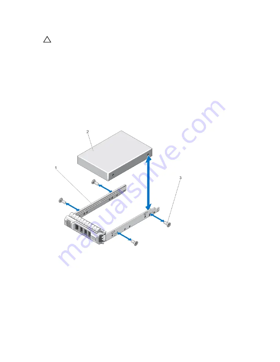
1.

Remove the screws from the slide rails on the hard-drive carrier.

2.

Lift the hard drive out of the hard-drive carrier.

Figure 23. Removing and Installing a Hard Drive Into a Hard-Drive Carrier

1. hard-drive carrier
2. hard drive
3. screws (4)

55

Содержание PowerEdge R720 t

Страница 1: ...Dell PowerEdge R720 and R720xd Owner s Manual Regulatory Model E14S Series Regulatory Type E14S001 ...

Страница 2: ... Sempron are trademarks of Advanced Micro Devices Inc Microsoft Windows Windows Server Internet Explorer MS DOS Windows Vista and Active Directory are either trademarks or registered trademarks of Microsoft Corporation in the United States and or other countries Red Hat and Red Hat Enterprise Linux are registered trademarks of Red Hat Inc in the United States and or other countries Novell and SUSE...

Страница 3: ... Setup 22 Responding To Error Messages 22 Using The System Setup Navigation Keys 22 System Setup Options 22 System Setup Main Screen 23 System BIOS Screen 23 System Information Screen 24 Memory Settings Screen 24 Processor Settings Screen 24 SATA Settings Screen 26 Boot Settings Screen 26 Integrated Devices Screen 27 Serial Communications Screen 28 System Profile Settings Screen 28 System Security...

Страница 4: ...ing Shroud 41 Installing The Cooling Shroud 42 System Memory 43 General Memory Module Installation Guidelines 45 Mode Specific Guidelines 46 Sample Memory Configurations 47 Removing Memory Modules 49 Installing Memory Modules 50 Hard Drives 51 Removing A 2 5 Inch Hard Drive Blank 51 Installing A 2 5 Inch Hard Drive Blank 52 Removing A 2 5 Inch Hard Drive Blank Back 52 Installing A 2 5 Inch Hard Dr...

Страница 5: ...d Riser 2 Or 3 68 Removing An Expansion Card From The Expansion Card Riser 1 69 Installing An Expansion Card Into The Expansion Card Riser 1 70 Removing Expansion Card Risers 71 Installing Expansion Card Risers 74 GPU Card Installation Guidelines 74 Installing A GPU Card 75 Removing A GPU Card 76 SD vFlash Card 77 Replacing An SD vFlash Card 77 Removing The vFlash Media Unit 78 Installing The vFla...

Страница 6: ...ntrol Panel PowerEdge R720 116 Installing The Control Panel PowerEdge R720 118 Removing The Control Panel PowerEdge R720xd 118 Installing The Control Panel PowerEdge R720xd 119 Removing The I O Panel PowerEdge R720xd 120 Installing The I O Panel PowerEdge R720xd 121 System Board 121 Removing The System Board 121 Installing The System Board 123 4 Troubleshooting Your System 125 Safety First For You...

Страница 7: ...gnostics 135 Dell Online Diagnostics 135 Dell Embedded System Diagnostics 135 When To Use The Embedded System Diagnostics 135 Running The Embedded System Diagnostics 135 System Diagnostic Controls 136 6 Jumpers And Connectors 137 System Board Jumper Settings 137 System Board Connectors 138 Disabling A Forgotten Password 140 7 Technical Specifications 141 8 System Messages 147 LCD Messages 147 View...

Страница 8: ...8 ...

Страница 9: ...iant operating systems turning off the system using the power button causes the system to perform a graceful shutdown before power to the system is turned off 2 NMI button Used to troubleshoot software and device driver errors when running certain operating systems This button can be pressed using the end of a paper clip Use this button only if directed to do so by qualified support personnel or b...

Страница 10: ...ue during normal system operation The LCD lights amber when the system needs attention and the LCD panel displays an error code followed by descriptive text NOTE If the system is connected to a power source and an error is detected the LCD lights amber regardless of whether the system is turned on or off 8 Optical drive optional One optional SATA DVD ROM drive or DVD RW drive 9 Hard drives 3 5 inc...

Страница 11: ...onding during POST press and hold the system ID button for more than five seconds to enter BIOS progress mode To reset the iDRAC if not disabled in F2 iDRAC setup press and hold the button for more than 15 seconds 3 Power on indicator power button The power on indicator lights when the system power is on The power button controls the power supply output to the system NOTE On ACPI compliant operati...

Страница 12: ... LCD panel provides system information and status and error messages to indicate when the system is operating correctly or when the system needs attention See System Error Messages for information about specific error codes The LCD backlight lights blue during normal operating conditions and lights amber to indicate an error condition The LCD backlight is off when the system is in standby mode and...

Страница 13: ...e proceeding to the next action Option Description iDRAC Select DHCP or Static IP to configure the network mode If Static IP is selected the available fields are IP Subnet Sub and Gateway Gtw Select Setup DNS to enable DNS and to view domain addresses Two separate DNS entries are available Set error Select SEL to display LCD error messages in a format that matches the IPMI description in the SEL T...

Страница 14: ...nto a working power source and press the power button The following section describes system conditions and possible corrective actions associated with these indicators Health indicator Condition Corrective Action If the system is on and in good health the indicator lights solid blue None required The indicator blinks amber if the system is on or in standby and any error exists for example a faile...

Страница 15: ...erature out of range or fan failure Ensure that none of the following conditions exist A cooling fan is removed or has failed System cover cooling shroud EMI filler panel memory module blank or back filler bracket is removed Ambient temperature is too high External airflow is obstructed See Getting Help Memory indicator Condition Corrective Action The indicator blinks amber if a memory error occur...

Страница 16: ...n Blinks green two times per second Identifying drive or preparing for removal Off Drive ready for insertion or removal NOTE The drive status indicator remains off until all hard drives are initialized after the system is turned on Drives are not ready for insertion or removal during this time Blinks green amber and off Predicted drive failure Blinks amber four times per second Drive failed Blinks...

Страница 17: ...n the back flashes until one of the buttons is pressed again PowerEdge R720xd When one of these buttons is pressed the system status indicator on the back flashes until one of the buttons is pressed again Press to toggle the system ID on and off If the system stops responding during POST press and hold the system ID button for more than five seconds to enter BIOS progress mode To reset iDRAC if no...

Страница 18: ...tors Four integrated 10 100 1000 Mbps NIC connectors or Four integrated connectors that include Two 10 100 1000 Mbps NIC connectors Two 100 Mbps 1 Gbps 10 Gbps SFP 10 GbE T connectors 9 PCIe expansion card slots full height 4 PowerEdge R720 Allows you to connect up to four full height PCI Express expansion cards PCIe expansion card slots full height 3 PowerEdge R720xd Allows you to connect up to t...

Страница 19: ... to a valid network at less than its maximum port speed Activity indicator is blinking green Network data is being sent or received Power Indicator Codes Each AC power supply has an illuminated translucent handle and each DC power supply when available has an LED that serves as an indicator to show whether power is present or whether a power fault has occurred Figure 10 AC Power Supply Status Indi...

Страница 20: ...dicates that the power supply is mismatched with the other power supply in terms of efficiency feature set health status and supported voltage Replace the power supply that has the flashing indicator with a power supply that matches the capacity of the other installed power supply Other Information You May Need WARNING See the safety and regulatory information that shipped with your system Warrant...

Страница 21: ...re configuration Enable or disable integrated devices Set performance and power management thresholds Manage system security You can access the System Setup using the Standard graphical browser which is enabled by default Text browser which is enabled using Console Redirection To enable Console Redirection in System Setup select System BIOS Serial Communication screen Serial Communication select O...

Страница 22: ...es If an error message is displayed while the system is booting make a note of the message For more information see System Error Messages NOTE After installing a memory upgrade it is normal for your system to display a message the first time you start your system Using The System Setup Navigation Keys Keys Action Up arrow Moves to the previous field Down arrow Moves to the next field Enter Allows ...

Страница 23: ...elated to the processor such as speed cache size and so on SATA Settings Displays options to enable or disable the integrated SATA controller and ports NOTE This setting is not available on the PowerEdge R720xd Boot Settings Displays options to specify the boot mode BIOS or UEFI Enables you to modify UEFI and BIOS boot settings Integrated Devices Displays options to enable or disable integrated de...

Страница 24: ...efault the System Memory Testing option is set to Disabled Memory Operating Mode Specifies the memory operating mode The options available depending on the memory configuration of your system are Optimizer Mode Advanced ECC Mode Mirror Mode Spare Mode and Spare with Advanced ECC Mode By default the Memory Operating Mode option is set to Optimizer Mode NOTE The Memory Operating Mode can have differ...

Страница 25: ...er By default the Hardware Prefetcher option is set to Enabled DCU Streamer Prefetcher Allows you to enable or disable Data Cache Unit streamer prefetcher By default the DCU Streamer Prefetcher option is set to Enabled DCU IP Prefetcher Allows you to enable or disable Data Cache Unit IP prefetcher By default the DCU IP Prefetcher option is set to Enabled Execute Disable Allows you enable or disabl...

Страница 26: ...to Auto Port F Auto enables BIOS support for the device attached to SATA port F By default Port F is set to Auto NOTE Ports A B C and D are used for the backplane drives port E for the optical drive CD DVD and port F for the tape drive Boot Settings Screen Menu Item Description Boot Mode Allows you to set the boot mode of the system CAUTION Switching the boot mode may prevent the system from booti...

Страница 27: ...DSDM is installed on the system board Internal SD Card Redundancy If set to Mirror mode data is written on both SD cards If any one of the SD card fails data is written to the active SD card Data from this card is copied to the replacement SD card at the next boot By default Internal SD Card Redundancy option is set to Mirror NOTE This option is displayed only if IDSDM is installed on the system b...

Страница 28: ...al connector to serial device 1 serial device 2 or remote access device By default the External Serial Connector option is set to Serial Device1 NOTE Only Serial Device 2 can be used for SOL To use console redirection by SOL configure the same port address for console redirection and the serial device Failsafe Baud Rate Displays the failsafe baud rate for console redirection The BIOS attempts to d...

Страница 29: ...on is set to Standard Memory Refresh Rate Allows you to set the memory refresh rate By default the Memory Refresh Rate option is set to 1x Memory Operating Voltage Allows you to set the DIMM voltage selection When set to Auto the system automatically sets the system voltage to the optimal setting based on the DIMM capacity and the numbers of DIMMs installed By default the Memory Operating Voltage ...

Страница 30: ...ble or disable the power button on the front of the system By default the Power Button option is set to Enabled NMI Button Allows you to enable or disable the NMI button on the front of the system By default the NMI Button option is set to Disabled AC Power Recovery Allows you to set how the system reacts after AC power is restored to the system By default the AC Power Recovery option is set to La...

Страница 31: ... Setup Password features For more information on the password jumper settings see System Board Jumper Settings You can assign a new System Password and or Setup Password or change an existing System Password and or Setup Password only when the password jumper setting is enabled and Password Status is Unlocked If the Password Status is Locked you cannot change the System Password and or Setup Passw...

Страница 32: ... or Tab 6 Select Setup Password alter or delete the existing setup password and press Enter or Tab NOTE If you change the System and or Setup password a message prompts you to re enter the new password If you delete the System and or Setup password a message prompts you to confirm the deletion 7 Press Esc to return to the System BIOS screen Press Esc again and a message prompts you to save the cha...

Страница 33: ...The UEFI Boot Manager NOTE Operating systems must be 64 bit UEFI compatible for example Microsoft Windows Server 2008 x64 version to be installed from the UEFI boot mode DOS and 32 bit operating systems can only be installed from the BIOS boot mode The Boot Manager enables you to Add delete and arrange boot options Access System Setup and BIOS level boot options without rebooting To enter the Boot...

Страница 34: ...Menu Displays a list of the drivers installed on the system and their health status Launch System Setup Enables you to access the System Setup System Utilities Enables you to access the BIOS Update File Explorer run the Dell Diagnostics program and reboot the system UEFI Boot Menu Menu Item Description Select UEFI Boot Option Displays the list of available UEFI boot options marked with asterisks s...

Страница 35: ...ettings Utility 1 Turn on or restart the managed system 2 Press F2 during Power on Self test POST 3 In the System Setup Main Menu page click iDRAC Settings The iDRAC Settings screen is displayed Changing The Thermal Settings The iDRAC Settings utility enables you to select and customize the thermal control settings for your system 1 Enter the iDRAC Settings utility 2 Under iDRAC Settings Thermal U...

Страница 36: ...36 ...

Страница 37: ...90871 1 hand crimping tool or equivalent Wire stripper pliers capable of removing insulation from size 10 AWG solid or stranded insulated copper wire NOTE Use alpha wire part number 3080 or equivalent 65 30 stranding Front Bezel Optional Removing The Front Bezel 1 Unlock the keylock at the left end of the bezel 2 Lift the release latch next to the keylock 3 Rotate the left end of the bezel away fr...

Страница 38: ... authorized in your product documentation or as directed by the online or telephone service and support team Damage due to servicing that is not authorized by Dell is not covered by your warranty Read and follow the safety instructions that came with the product CAUTION Do not operate the system without the cover for a duration exceeding five minutes Opening The System NOTE It is recommended that ...

Страница 39: ...ect the system to its electrical outlet and turn the system on including any attached peripherals Inside The System CAUTION Many repairs may only be done by a certified service technician You should only perform troubleshooting and simple repairs as authorized in your product documentation or as directed by the online or telephone service and support team Damage due to servicing that is not author...

Страница 40: ...able securing bracket 3 PCIe card holder 4 cooling shroud 5 expansion card riser 3 6 network daughter card 7 expansion card riser 2 8 expansion card riser 1 9 heat sink for processor 1 10 heat sink for processor 2 11 DIMMs 24 12 cooling fans 6 13 hard drive backplane 40 ...

Страница 41: ...or 1 12 heat sink for processor 2 13 DIMMs 24 14 cooling fans 6 Cooling Shroud Removing The Cooling Shroud CAUTION Many repairs may only be done by a certified service technician You should only perform troubleshooting and simple repairs as authorized in your product documentation or as directed by the online or telephone service and support team Damage due to servicing that is not authorized by D...

Страница 42: ...u should only perform troubleshooting and simple repairs as authorized in your product documentation or as directed by the online or telephone service and support team Damage due to servicing that is not authorized by Dell is not covered by your warranty Read and follow the safety instructions that came with the product NOTE For proper seating of the cooling shroud in the chassis ensure that the c...

Страница 43: ...ions DIMM configuration number of ranks maximum frequency of the DIMMs number of DIMMs populated per channel DIMM operating voltage system profile selected for example Performance Optimized Custom or Dense Configuration Optimized maximum supported DIMM frequency of the processors The system contains 24 memory sockets split into two sets of 12 sockets one set per processor Each 12 socket set is org...

Страница 44: ...llows Processor 1 channel 0 slots A1 A5 and A9 channel 1 slots A2 A6 and A10 channel 2 slots A3 A7 and A11 channel 3 slots A4 A8 and A12 Processor 2 channel 0 slots B1 B5 and B9 channel 1 slots B2 B6 and B10 channel 2 slots B3 B7 and B11 channel 3 slots B4 B8 and B12 44 ...

Страница 45: ... green release levers cannot be populated Up to three LRDIMMs can be populated regardless of rank count Populate DIMM sockets only if a processor is installed For single processor systems sockets A1 to A12 are available For dual processor systems sockets A1 to A12 and sockets B1 to B12 are available Populate all sockets with white release tabs first then black and then green Do not populate the th...

Страница 46: ...ng this feature must be enabled in the System Setup In this mode one rank per channel is reserved as a spare If persistent correctable errors are detected on a rank the data from this rank is copied to the spare rank and the failed rank is disabled With memory sparing enabled the system memory available to the operating system is reduced by one rank per channel For example in a dual processor conf...

Страница 47: ...T s 1R x8 1600 MT s A1 A2 A3 A4 12 2 6 1R x8 1333 MT s 1R x8 1600 MT s A1 A2 A3 A4 A5 A6 16 2 8 1R x8 1333 MT s A1 A2 A3 A4 A5 A6 A7 A8 4 4 2R x8 1333 MT s 2R x8 1600 MT s A1 A2 A3 A4 24 2 12 1R x8 1333 MT s A1 A2 A3 A4 A5 A6 A7 A8 A9 A10 A11 A12 4 6 2R x8 1333 MT s 2R x8 1600 MT s A1 A2 A3 A4 A5 A6 48 4 12 2R x8 1333 MT s A1 A2 A3 A4 A5 A6 A7 A8 A9 A10 A11 A12 8 6 2R x4 1333 MT s 2R x4 1600 MT s ...

Страница 48: ...R x4 1333 MT s 2R x4 1600 MT s A1 A2 A3 A4 B1 B2 B3 B4 96 4 24 2R x8 1333 MT s A1 A2 A3 A4 A5 A6 A7 A8 A9 A10 A11 A12 B1 B2 B3 B4 B5 B6 B7 B8 B9 B10 B11 B12 8 12 2R x4 1333 MT s 2R x4 1600 MT s A1 A2 A3 A4 A5 A6 B1 B2 B3 B4 B5 B6 128 8 16 2R x4 1333 MT s A1 A2 A3 A4 A5 A6 A7 A8 B1 B2 B3 B4 B5 B6 B7 B8 16 8 2R x4 1333 MT s 2R x4 1600 MT s A1 A2 A3 A4 B1 B2 B3 B4 160 8 20 2R x4 1333 MT s A1 A2 A3 A4...

Страница 49: ... the memory module CAUTION Many repairs may only be done by a certified service technician You should only perform troubleshooting and simple repairs as authorized in your product documentation or as directed by the online or telephone service and support team Damage due to servicing that is not authorized by Dell is not covered by your warranty Read and follow the safety instructions that came wi...

Страница 50: ...cian You should only perform troubleshooting and simple repairs as authorized in your product documentation or as directed by the online or telephone service and support team Damage due to servicing that is not authorized by Dell is not covered by your warranty Read and follow the safety instructions that came with the product CAUTION To ensure proper system cooling memory module blanks must be in...

Страница 51: ...emory modules may not be installed properly Repeat step 4 through step 7 of this procedure checking to ensure that the memory modules are firmly seated in their sockets 14 Run the appropriate diagnostic test For more information see Using System Diagnostics Hard Drives All hard drives connect to the system board through the hard drive backplane Hard drives are supplied in hot swappable hard drive ...

Страница 52: ...the release button clicks into place 3 If applicable install the front bezel Removing A 2 5 Inch Hard Drive Blank Back NOTE This procedure applies only to PowerEdge R720xd CAUTION To maintain proper system cooling all empty hard drive slots must have drive blanks installed Pull the hard drive blank out until it is free of the hard drive slot Figure 20 Removing and Installing a 2 5 Inch Hard Drive ...

Страница 53: ...alling a 3 5 Inch Hard Drive Blank 1 hard drive blank 2 release button Installing A 3 5 Inch Hard Drive Blank 1 If installed remove the front bezel 2 Insert the hard drive blank into the hard drive slot until the release button clicks into place 3 If applicable install the front bezel Removing A Hot Swap Hard Drive CAUTION To prevent data loss ensure that your operating system supports hot swap dr...

Страница 54: ...rform troubleshooting and simple repairs as authorized in your product documentation or as directed by the online or telephone service and support team Damage due to servicing that is not authorized by Dell is not covered by your warranty Read and follow the safety instructions that came with the product CAUTION Use only hard drives that have been tested and approved for use with the hard drive ba...

Страница 55: ...it 2 Install a hard drive in the hard drive carrier 3 Press the release button on the front of the hard drive carrier and open the hard drive carrier handle 4 Insert the hard drive carrier into the hard drive slot until the carrier connects with the backplane 5 Close the hard drive carrier handle to lock the hard drive in place Removing A Hard Drive From A Hard Drive Carrier 1 Remove the screws fr...

Страница 56: ...pairs as authorized in your product documentation or as directed by the online or telephone service and support team Damage due to servicing that is not authorized by Dell is not covered by your warranty Read and follow the safety instructions that came with the product 1 If installed remove the front bezel 2 Turn off the system including any attached peripherals and disconnect the system from the...

Страница 57: ...ezel 2 Turn off the system including any attached peripherals and disconnect the system from its electrical outlet 3 Open the system 4 To remove the optical drive blank press the blue release tab at the back of the blank and push the blank out of the system 5 Align the optical drive with the optical drive slot on the front of chassis 6 Slide the optical drive into the slot until the latch snaps in...

Страница 58: ... perform troubleshooting and simple repairs as authorized in your product documentation or as directed by the online or telephone service and support team Damage due to servicing that is not authorized by Dell is not covered by your warranty Read and follow the safety instructions that came with the product CAUTION The cooling fans are hot swappable To maintain proper cooling while the system is o...

Страница 59: ...the connector on the system board 3 Slide the cooling fan into the securing slots until the tabs lock into place 4 Close the system Removing The Cooling Fan Assembly CAUTION Many repairs may only be done by a certified service technician You should only perform troubleshooting and simple repairs as authorized in your product documentation or as directed by the online or telephone service and suppo...

Страница 60: ... not authorized by Dell is not covered by your warranty Read and follow the safety instructions that came with the product CAUTION Ensure that the cables are correctly installed and retained by the cable retention bracket before installing the cooling fan assembly Incorrectly installed cables may get damaged 1 Align the cooling fan assembly slots with the guide pins on the chassis 2 Slide the cool...

Страница 61: ...d in your product documentation or as directed by the online or telephone service and support team Damage due to servicing that is not authorized by Dell is not covered by your warranty Read and follow the safety instructions that came with the product 1 Turn off the system including any attached peripherals and disconnect the system from the electrical outlet and peripherals 2 Open the system 3 L...

Страница 62: ...TION Do not use your system without the PCIe card holder installed The PCIe card holder is necessary to ensure proper system cooling 1 Turn off the system including any attached peripherals and disconnect the system from the electrical outlet and peripherals 2 Open the system 3 If installed remove the full length PCIe card 4 Press the release tab and the touch point to release the PCIe card holder...

Страница 63: ... and turn the system on including any attached peripherals Opening And Closing The PCIe Card Holder Latch CAUTION Many repairs may only be done by a certified service technician You should only perform troubleshooting and simple repairs as authorized in your product documentation or as directed by the online or telephone service and support team Damage due to servicing that is not authorized by De...

Страница 64: ... to servicing that is not authorized by Dell is not covered by your warranty Read and follow the safety instructions that came with the product 1 Turn off the system including any attached peripherals and disconnect the system from the electrical outlet and peripherals 2 Open the system 3 Remove the cooling shroud 4 Remove all cables routed through the cable retention bracket 5 Press the tab and s...

Страница 65: ...s And Expansion Card Risers NOTE A missing or an unsupported expansion card riser logs an SEL event It does not prevent your system from powering on and no BIOS POST message or F1 F2 pause is displayed Expansion Card Installation Guidelines Depending on your system configuration PowerEdge R720 supports seven expansion cards PowerEdge R720xd supports six expansion cards The following PCI Express Ge...

Страница 66: ...de 6 4 6 Not Supported Not Supported 2 0 GPU single wide 4 6 7 5 6 7 5 Not Supported Not Supported 4 0 3 GPU Host Interface Card HIC 4 6 6 Not Supported Not Supported 2 0 4 RAID H810 7 6 4 5 7 6 5 6 4 5 6 5 4 3 RAID H710P 2 Not Supported Not Supported Not Supported 1 0 5 FC16 HBA Full Height FH 5 7 4 6 5 7 6 4 6 5 6 5 4 3 Low Profile LP 2 3 1 Not Supported 2 3 1 Not Supported 3 3 6 Converged Netwo...

Страница 67: ...not covered by your warranty Read and follow the safety instructions that came with the product 1 Turn off the system including any attached peripherals and disconnect the system from the electrical outlet and peripherals 2 Open the system 3 Disconnect any cables connected to the expansion card 4 Lift the expansion card latch out of the slot 5 Grasp the expansion card by its edges and remove it fr...

Страница 68: ...zed in your product documentation or as directed by the online or telephone service and support team Damage due to servicing that is not authorized by Dell is not covered by your warranty Read and follow the safety instructions that came with the product 1 Unpack the expansion card and prepare it for installation For instructions see the documentation accompanying the card 2 Turn off the system in...

Страница 69: ... online or telephone service and support team Damage due to servicing that is not authorized by Dell is not covered by your warranty Read and follow the safety instructions that came with the product NOTE The expansion card riser 1 can be used only when both the processors are installed 1 Turn off the system including any attached peripherals and disconnect the system from the electrical outlet an...

Страница 70: ...ized by Dell is not covered by your warranty Read and follow the safety instructions that came with the product NOTE The expansion card riser 1 can be used only when both the processors are installed 1 Unpack the expansion card and prepare it for installation For instructions see the documentation accompanying the card 2 Turn off the system including any attached peripherals and disconnect the sys...

Страница 71: ... as authorized in your product documentation or as directed by the online or telephone service and support team Damage due to servicing that is not authorized by Dell is not covered by your warranty Read and follow the safety instructions that came with the product NOTE The expansion card riser 1 can be used only when both the processors are installed 1 Turn off the system including any attached p...

Страница 72: ... expansion card slot 1 2 expansion card slot 2 3 expansion card slot 3 Figure 35 Removing and Installing the Expansion Card Riser 2 1 power connector for GPU cards 2 expansion card riser 2 3 riser guide back 4 expansion card riser 2 connector 5 riser guide front 72 ...

Страница 73: ...n switch 2 expansion card slot 4 3 expansion card slot 5 4 power connector for GPU cards Figure 37 Removing and Installing the Expansion Card Riser 3 1 riser guide front 2 power connector for GPU cards 3 expansion card riser 3 4 expansion card riser 3 connector 5 riser guide back 73 ...

Страница 74: ... card riser 2 Align the expansion card riser with the connector and the riser guide pin on the system board 3 Lower the expansion card riser into place until the expansion card riser is fully seated in the connector 4 Close the system 5 Reconnect the system to its electrical outlet and turn the system on including any attached peripherals 6 Install any device drivers required for the card as descr...

Страница 75: ...A GPU Card CAUTION Many repairs may only be done by a certified service technician You should only perform troubleshooting and simple repairs as authorized in your product documentation or as directed by the online or telephone service and support team Damage due to servicing that is not authorized by Dell is not covered by your warranty Read and follow the safety instructions that came with the p...

Страница 76: ...ard CAUTION Many repairs may only be done by a certified service technician You should only perform troubleshooting and simple repairs as authorized in your product documentation or as directed by the online or telephone service and support team Damage due to servicing that is not authorized by Dell is not covered by your warranty Read and follow the safety instructions that came with the product ...

Страница 77: ...t provides persistent on demand local storage and a custom deployment environment that allows automation of server configuration scripts and imaging It emulates USB device s For more information see the iDRAC7 User s Guide at support dell com manuals Replacing An SD vFlash Card 1 Locate the vFlash media slot on the system 2 To remove the installed SD vFlash card push inward on the card to release ...

Страница 78: ...pairs as authorized in your product documentation or as directed by the online or telephone service and support team Damage due to servicing that is not authorized by Dell is not covered by your warranty Read and follow the safety instructions that came with the product 1 Turn off the system including any attached peripherals and disconnect the system from the electrical outlet and peripherals 2 O...

Страница 79: ...ice and support team Damage due to servicing that is not authorized by Dell is not covered by your warranty Read and follow the safety instructions that came with the product 1 Turn off the system including any attached peripherals and disconnect the system from its electrical outlet 2 Open the system 3 Slide in and align the vFlash media unit toward the back of chassis 4 Connect the cable to the ...

Страница 80: ... covered by your warranty Read and follow the safety instructions that came with the product 1 Turn off the system including any attached peripherals and disconnect the system from the electrical outlet and peripherals 2 Open the system 3 Remove the expansion card riser 3 and any card s installed in the riser 4 Locate the internal dual SD module installed on the J_IDSDM connector on the system boa...

Страница 81: ...cing that is not authorized by Dell is not covered by your warranty Read and follow the safety instructions that came with the product 1 Turn off the system including any attached peripherals and disconnect the system from the electrical outlet and peripherals 2 Open the system 3 Remove the expansion card riser cage 3 and any card s installed in the riser 4 Locate the J_IDSDM connector on the syst...

Страница 82: ... service technician You should only perform troubleshooting and simple repairs as authorized in your product documentation or as directed by the online or telephone service and support team Damage due to servicing that is not authorized by Dell is not covered by your warranty Read and follow the safety instructions that came with the product NOTE To use an SD card with your system ensure that the ...

Страница 83: ...came with the product 1 Turn off the system including any attached peripherals and disconnect the system from the electrical outlet and peripherals 2 Open the system 3 Remove the cooling shroud 4 Remove the expansion card riser 1 5 Push down the two release levers at the edge of the card to disengage the card from the connector 6 Angle the card so that the other end of the card disengages from the...

Страница 84: ...d 10 Close the system 11 Reconnect the system to its electrical outlet and turn the system on including any attached peripherals Network Daughter Card Removing The Network Daughter Card CAUTION Many repairs may only be done by a certified service technician You should only perform troubleshooting and simple repairs as authorized in your product documentation or as directed by the online or telepho...

Страница 85: ...ad and follow the safety instructions that came with the product 1 Angle the card so that the RJ 45 connectors fit through the slot in the back panel 2 Align the captive screws at back end of the card with the captive screw sockets on the system board 3 Press the touch point on the card until the card connector is firmly seated on the system board connector 4 Using a 2 Phillips screwdriver tighten...

Страница 86: ... the system BIOS using the Lifecycle Controller 2 Turn off the system including any attached peripherals and disconnect the system from the electrical outlet When disconnected from the power source press and hold the power button for three seconds to fully drain the system of stored power prior to removing the cover 3 Open the system 4 Remove the cooling shroud WARNING The heat sink and processor ...

Страница 87: ... suddenly if not firmly grasped 8 Position your thumb firmly over the processor socket release lever near the unlock icon and release the lever from the locked position by pushing down and out from under the tab 9 Similarly position your thumb firmly over the processor socket release lever near the lock icon and release the lever from the locked position by pushing down and out from under the tab ...

Страница 88: ... and can be permanently damaged Be careful not to bend the pins in the socket when removing the processor out of the socket 11 Lift the processor out of the socket and leave the release lever up so that the socket is ready for the new processor NOTE If you are permanently removing a processor you must install a processor DIMM blank in the vacant socket to ensure proper system cooling The processor...

Страница 89: ...ne or telephone service and support team Damage due to servicing that is not authorized by Dell is not covered by your warranty Read and follow the safety instructions that came with the product NOTE If you are installing a single processor it must be installed in socket CPU1 1 Before upgrading your system download the latest system BIOS version from support dell com and follow the instructions in...

Страница 90: ...otate the socket release lever near the lock icon until it is locked in position 11 Similarly rotate the socket release lever near the unlock icon until it is locked in position 12 Using a clean lint free cloth remove the thermal grease from the heat sink CAUTION Applying too much thermal grease can result in excess grease coming in contact with and contaminating the processor socket 13 Open the g...

Страница 91: ...er supply in a sleep state The power supply defaults are to wake both power supplies if the load on the active power supply is greater than 50 and to sleep the redundant power supply if the load falls below 20 You can configure the Hot Spare feature using the iDRAC settings For more information on iDRAC settings see the iDRAC7 User s Guide at support dell com manuals Removing An AC Power Supply CA...

Страница 92: ...output power NOTE The maximum output power shown in Watts is listed on the power supply label 2 If applicable remove the power supply blank 3 Slide the new power supply into the chassis until the power supply is fully seated and the release latch snaps into place NOTE If you unlatched the cable management arm re latch it For information about the cable management arm see the system s rack document...

Страница 93: ...t Requirements Supply voltage 48 60 V DC Current consumption 32 A maximum Kit Contents Dell part number 6RYJ9 terminal block or equivalent 1 6 32 nut equipped with lock washer 1 Required Tools Wire stripper pliers capable of removing insulation from size 10 AWG solid or stranded insulated copper wire NOTE Use alpha wire part number 3080 or equivalent 65 30 stranding Required Wires One UL 10 AWG 2 ...

Страница 94: ...o servicing that is not authorized by Dell is not covered by your warranty Read and follow all safety instructions that came with the product 1 Strip the insulation from the ends of the DC power wires exposing approximately 13 mm 0 5 inch of copper wire WARNING Reversing polarity when connecting DC power wires can permanently damage the power supply or the system 2 Insert the copper ends into the ...

Страница 95: ...ot authorized by Dell is not covered by your warranty Read and follow all safety instructions that came with the product CAUTION The system requires one power supply for normal operation On power redundant systems remove and replace only one power supply at a time in a system that is powered on NOTE You may have to unlatch and lift the optional cable management arm if it interferes with power supp...

Страница 96: ... maximum output power NOTE The maximum output power shown in Watts is listed on the power supply label 2 If applicable remove the power supply blank 3 Slide the new power supply into the chassis until the power supply is fully seated and the release latch snaps into place NOTE If you unlatched the cable management arm re latch it For information about the cable management arm see the system s rack...

Страница 97: ... Removing and Installing the Power Supply Blank 1 power supply blank Installing The Power Supply Blank NOTE Install the power supply blank only in the second power supply bay To install the power supply blank align the blank with the power supply bay and insert it into the chassis until it clicks into place System Battery Replacing The System Battery WARNING There is a danger of a new battery expl...

Страница 98: ...essing down firmly on the positive side of the connector Figure 53 Replacing the System Battery 1 positive side of battery connector 2 system battery 3 negative side of battery connector 6 Lift the battery out of the securing tabs at the negative side of the connector 7 To install a new system battery support the battery connector by pressing down firmly on the positive side of the connector 8 Hol...

Страница 99: ...online or telephone service and support team Damage due to servicing that is not authorized by Dell is not covered by your warranty Read and follow the safety instructions that came with the product 1 If installed remove the front bezel 2 Turn off the system including any attached peripherals and disconnect the system from the electrical outlet 3 Open the system CAUTION To prevent damage to the dr...

Страница 100: ...re 54 Removing and Installing the 3 5 Inch x8 SAS SATA Backplane PowerEdge R720 1 release tabs 2 2 SAS A cable 3 backplane signal cable 4 backplane power cable A 5 SAS B cable 6 backplane power cable B 100 ...

Страница 101: ...iagram 3 5 Inch x8 SAS SATA Backplane PowerEdge R720 1 cable retention bracket 2 system board 3 integrated storage controller card 4 SAS connector mini PERC SAS on the system board 5 SAS connectors on the backplane 2 101 ...

Страница 102: ...Figure 56 Cabling Diagram 3 5 Inch x4 SAS SATA Backplane PowerEdge R720 1 cable retention bracket 2 system board 3 SAS connector on the system board 4 SAS connector on the backplane 102 ...

Страница 103: ...g and Installing the 2 5 Inch x16 SAS SATA Backplane PowerEdge R720 1 x16 hard drive backplane 2 hard drive backplane connectors 16 3 backplane power cables 2 4 backplane signal cable 5 SAS cables 2 6 release tabs 2 103 ...

Страница 104: ...bling Diagram 2 5 Inch x16 SAS SATA Backplane PowerEdge R720 1 cable retention bracket 2 system board 3 integrated storage controller card 4 SAS connector on the system board 5 SAS connectors on the backplane 2 104 ...

Страница 105: ...oving and Installing the 2 5 Inch x8 SAS SATA Backplane PowerEdge R720 1 x8 hard drive backplane 2 hard drive backplane connectors 8 3 release tab 4 backplane power cable 5 SAS cables 2 6 backplane signal cable 105 ...

Страница 106: ...am Dual 2 5 Inch x8 SAS SATA Backplane PowerEdge R720 1 system board 2 cable retention bracket 3 integrated storage controller card 4 SAS connector on the system board 5 SAS controller card 6 SAS backplane 7 SAS backplane 106 ...

Страница 107: ...the 2 5 Inch x4 SSD Dell PowerEdge Express Flash PCIe SSD Backplane PowerEdge R720 1 hard drive backplane connectors 4 2 x4 hard drive backplane 3 release tab 4 SSD PCIe SSD cables 4 5 backplane power cable 6 backplane signal cable 107 ...

Страница 108: ...SAS SATA and x4 PCIe SSD Backplane PowerEdge R720 1 cable retention bracket 2 system board 3 integrated storage controller card 4 SSD PCIe SSD controller card 5 SAS connector on the system board 6 SSD PCIe SSD backplane 7 SAS backplane 108 ...

Страница 109: ...owerEdge R720xd 1 release tabs 2 2 pass through I2C cable 3 left control panel cable 4 I2C cable 5 power cable A 6 USB cable 7 SAS cables 3 8 power cable B 9 front I O cable 10 right control panel cable 11 x12 hard drive backplane 12 hard drive backplane connectors 12 109 ...

Страница 110: ...re 64 Cabling Diagram 3 5 Iinch x12 SAS SATA Backplane PowerEdge R720xd 1 cable retention bracket 2 system board 3 integrated storage controller card 4 SAS connector on the system board 5 SAS backplane 110 ...

Страница 111: ... drive backplane 2 left control panel cable 3 release tabs 2 4 power cable A 5 sideband cable 6 pass through I2C cable 7 SAS cables 3 8 power cable B 9 backplane expander bracket 10 right control panel cable 11 power cable C 12 front I O cable 13 USB cable 14 hard drive backplane connectors 24 111 ...

Страница 112: ...s as authorized in your product documentation or as directed by the online or telephone service and support team Damage due to servicing that is not authorized by Dell is not covered by your warranty Read and follow the safety instructions that came with the product 1 Use the hooks at the base of the chassis as guides to align the hard drive backplane 2 Slide down the hard drive backplane until th...

Страница 113: ...eam Damage due to servicing that is not authorized by Dell is not covered by your warranty Read and follow the safety instructions that came with the product 1 Turn off the system including any attached peripherals and disconnect the system from the electrical outlet 2 Open the system CAUTION To prevent damage to the drives and backplane you must remove the hard drives from the system before remov...

Страница 114: ...ing and Installing the Optional 2 5 Inch x2 Hard Drive Backplane PowerEdge R720xd 1 pass through I2C cable 2 I2C cable 3 sideband cable 4 hard drive backplane back 5 SAS SATA connectors 2 6 SAS cable 7 release pin 114 ...

Страница 115: ...ertified service technician You should only perform troubleshooting and simple repairs as authorized in your product documentation or as directed by the online or telephone service and support team Damage due to servicing that is not authorized by Dell is not covered by your warranty Read and follow the safety instructions that came with the product 1 Turn off the system including any attached per...

Страница 116: ...by Dell is not covered by your warranty Read and follow the safety instructions that came with the product 1 If installed remove the front bezel 2 Turn off the system including any attached peripherals and disconnect the system from the electrical outlet and peripherals 3 Open the system 4 Using a 2 Phillips screwdriver remove the screw s securing the control panel to the chassis CAUTION Do not us...

Страница 117: ... 4 USB connector cable 5 vFlash media connector cable 6 screws 2 7 Locate and press the tabs on the information tag 8 Push the information tag out of the slot to remove it from the control panel NOTE Retain the information tag for replacement in the new control panel Figure 71 Removing and Installing the Information Tag 1 information tag 2 tabs 2 3 slot 117 ...

Страница 118: ...d peripherals to their power sources and turn them on 7 If applicable install the front bezel Removing The Control Panel PowerEdge R720xd CAUTION Many repairs may only be done by a certified service technician You should only perform troubleshooting and simple repairs as authorized in your product documentation or as directed by the online or telephone service and support team Damage due to servic...

Страница 119: ...me with the product 1 If installed remove the front bezel 2 Turn off the system including any attached peripherals and disconnect the system from the electrical outlet and peripherals 3 Open the system 4 Fold the label around the cable 5 Fold the pull tab close to the connector and guide the connector and pull tab into the channel 6 Push the cable until the cable passes completely through the chan...

Страница 120: ...ff the system including any attached peripherals and disconnect the system from the electrical outlet and peripherals 3 Open the system CAUTION To prevent damage to the I O cable you must release the locking tab before removing or installing the I O cable from the connector on the hard drive backplane 4 Rotate the locking tab on the I O cable connector clockwise 90 degrees to release the lock 5 Di...

Страница 121: ...en the three Torx screws to secure the control panel to the chassis NOTE You must route the cable properly to prevent it from being pinched or crimped 10 Close the system 11 Reconnect the system to its electrical outlet and turn the system on including any attached peripherals 12 If applicable install the front bezel System Board Removing The System Board CAUTION Many repairs may only be done by a...

Страница 122: ...m the system board a Push the mini SAS cable connector to slide it further into the connector J_SASX8 on the system board b Press down and hold the metal tab on the mini SAS cable connector c Pull the mini SAS cable out of the connector on the system board a mini SAS cable connector b metal tab c connector on the system board 6 Disconnect all cables from the system board CAUTION Take care not to d...

Страница 123: ...repairs may only be done by a certified service technician You should only perform troubleshooting and simple repairs as authorized in your product documentation or as directed by the online or telephone service and support team Damage due to servicing that is not authorized by Dell is not covered by your warranty Read and follow the safety instructions that came with the product 1 Unpack the new ...

Страница 124: ...card d internal USB key if installed e internal dual SD module f all expansion card risers g cooling fan assembly h cooling shroud i power supply s 6 Reconnect all cables to the system board NOTE Ensure that the cables inside the system are routed along the chassis wall and secured using the cable securing bracket 7 Close the system 8 Reconnect the system to its electrical outlet and turn the syst...

Страница 125: ...ecurely attached to the external connectors on your system before troubleshooting any external devices Troubleshooting The Video Subsystem 1 Check the system and power connections to the monitor 2 Check the video interface cabling from the system to the monitor 3 Run the appropriate diagnostic test If the tests run successfully the problem is not related to video hardware If the tests fail see Get...

Страница 126: ...for any system messages pertaining to the NIC controller 3 Check the appropriate indicator on the NIC connector If the link indicator does not light check all cable connections If the activity indicator does not light the network driver files might be damaged or missing Remove and reinstall the drivers if applicable See the NIC s documentation If applicable change the autonegotiation setting Use a...

Страница 127: ...em CAUTION Many repairs may only be done by a certified service technician You should only perform troubleshooting and simple repairs as authorized in your product documentation or as directed by the online or telephone service and support team Damage due to servicing that is not authorized by Dell is not covered by your warranty Read and follow the safety instructions that came with the product 1...

Страница 128: ...efective battery Troubleshooting Power Supplies CAUTION Many repairs may only be done by a certified service technician You should only perform troubleshooting and simple repairs as authorized in your product documentation or as directed by the online or telephone service and support team Damage due to servicing that is not authorized by Dell is not covered by your warranty Read and follow the saf...

Страница 129: ...ripherals and unplug the system from the power source Wait at least 10 seconds and then reconnect the system to power 3 Turn on the system and attached peripherals and note the messages on the screen If an error message is displayed indicating a fault with a specific memory module go to step 12 4 Enter the System Setup and check the system memory setting Make any changes to the memory settings if ...

Страница 130: ...CAUTION Many repairs may only be done by a certified service technician You should only perform troubleshooting and simple repairs as authorized in your product documentation or as directed by the online or telephone service and support team Damage due to servicing that is not authorized by Dell is not covered by your warranty Read and follow the safety instructions that came with the product NOTE...

Страница 131: ...le is properly connected to the drive 9 Close the system If the problem is not resolved see Getting Help Troubleshooting A Tape Backup Unit CAUTION Many repairs may only be done by a certified service technician You should only perform troubleshooting and simple repairs as authorized in your product documentation or as directed by the online or telephone service and support team Damage due to serv...

Страница 132: ...card are installed and are configured correctly See the operating system documentation for more information 4 Restart the system and enter the System Setup 5 Verify that the controller is enabled and the drives are displayed in the System Setup If the problem persists try troubleshooting the expansion cards or see Getting Help Troubleshooting A Storage Controller CAUTION Many repairs may only be d...

Страница 133: ... instructions that came with the product NOTE When troubleshooting an expansion card see the documentation for your operating system and the expansion card 1 Run the appropriate diagnostic test For more information see Using System Diagnostics 2 Turn off the system and attached peripherals and disconnect the system from the electrical outlet 3 Open the system 4 Ensure that each expansion card is f...

Страница 134: ...covered by your warranty Read and follow the safety instructions that came with the product 1 Run the appropriate diagnostics test See Using System Diagnostics for available diagnostic tests 2 Turn off the system and attached peripherals and disconnect the system from the electrical outlet 3 Open the system 4 Ensure that the processor and heat sink are properly installed 5 Close the system 6 Run t...

Страница 135: ...werEdge Diagnostics User s Guide under Software Serviceability Tools at support dell com manuals Dell Embedded System Diagnostics NOTE Also known as Enhanced Pre boot System Assessment ePSA diagnostics The embedded system diagnostics provides a set of options for particular device groups or devices allowing you to Run tests automatically or in an interactive mode Repeat tests Display or save test ...

Страница 136: ...tatus information of all detected devices Results Displays the results of all tests that are executed System Health Provides the current overview of the system performance Event Log Displays a time stamped log of the results of all tests run on the system This is displayed if at least one event description is recorded For information about embedded system diagnostics see the Dell Enhanced Pre boot...

Страница 137: ...System Board Jumper Settings Jumper Setting Description PWRD_EN default The password feature is enabled pins 4 6 The password feature is disabled pins 2 4 iDRAC local access is unlocked at the next AC power cycle NVRAM_CLR default The configuration settings are retained at system boot pins 1 3 The configuration settings are cleared at the next system boot pins 3 5 137 ...

Страница 138: ..._CD Optical drive SATA connector 3 J_SATA_TBU Tape backup unit SATA connector 4 J_BP0 Optical drive power connector 5 J_TBU Tape backup unit power connector 6 J_PS1 PSU 1 power connector 7 J_IDSDM Internal dual SD module connector 8 J_NDC Network daughter card connector 9 J_RISER_3A Riser 3 connector 10 J_RISER_3B Riser 3 connector 138 ...

Страница 139: ...ID 25 BAT Battery connector 26 CPU2 Processor socket 2 27 B10 B6 B2 B9 B5 B1 Memory module sockets 28 J_BP3 Backplane power connector 29 J_BP_SIG3 Backplane signal connector 3 30 J_FAN2U_6 Cooling fan connector 31 J_BP_SIG2 Backplane signal connector 2 32 J_FAN2U_5 Cooling fan connector 33 J_BP2 Backplane power connector 34 J_FAN2U_4 Cooling fan connector 35 A10 A6 A2 A9 A5 A1 B3 B7 B11 B4 B8 B12 ...

Страница 140: ...nnect the system from the electrical outlet 2 Open the system 3 Move the jumper on the system board jumper from pins 4 and 6 to pins 2 and 4 4 Close the system The existing passwords are not disabled erased until the system boots with the Jumper on pins 2 and 4 However before you assign a new system and or setup password you must move the jumper back to pins 4 and 6 NOTE If you assign a new system...

Страница 141: ...ength x16 link NOTE To use slots 1 through 4 both the processors must be installed Slot 5 One full height full length x8 link Riser 3 default Slot 6 One full height full length x8 link PowerEdge R720 Slot 7 One full height full length x8 link PowerEdge R720 Riser 3 alternate for GPU Slot 6 One full height full length x16 link Memory Architecture 800 MT s 1066 MT s 1333 MT s or 1600 MT s DDR3 regis...

Страница 142: ...drive slots 0 through 7 Sixteen or eight plus eight hard drive systems Up to sixteen 2 5 inch internal hot swappable SAS SATA SATA SSD or Nearline SAS hard drives in hard drive slots 0 through 15 or 0 through 7 and 0 through 7 Twelve hard drive systems Up to eight 2 5 inch internal hot swappable SAS SATA SATA SSD or Nearline SAS hard drives in hard drive slots 0 through 7 hard drive bay 1 and up t...

Страница 143: ...he card slot is available for use only if the iDRAC7 Enterprise license is installed on your system Front USB Two 4 pin USB 2 0 compliant PowerEdge R720 One 4 pin USB 2 0 compliant PowerEdge R720xd Video 15 pin VGA External vFlash card PowerEdge R720 One flash memory card slot with iDRAC7 Enterprise card NOTE The card slot is available for use only if the iDRAC7 Enterprise license is installed on ...

Страница 144: ...stem can operate down to 5 C or up to 45 C for a maximum of 1 of its annual operating hours For temperatures between 40 C and 45 C de rate maximum allowable dry bulb temperature by 1 C per 125 m above 950 m 1 F per 228 ft Expanded Operating Temperature Restrictions Do not perform a cold startup below 5 C The operating temperature specified is for a maximum altitude of 3050 m 10 000 ft 130 W 4 core...

Страница 145: ...5 RH with 33 C 91 F maximum dew point Atmosphere must be non condensing at all times Maximum Vibration Operating 0 26 Grms at 5 Hz to 350 Hz all operation orientations Storage 1 87 Grms at 10 Hz to 500 Hz for 15 min all six sides tested Maximum Shock Operating One shock pulse in the positive z axis of 31 G for 2 6 ms in all operational orientations Storage Six consecutively executed shock pulses i...

Страница 146: ... be used outside a data center in environments such as an office or factory floor Data center air filtration as defined by ISO Class 8 per ISO 14644 1 with a 95 upper confidence limit NOTE Air entering the data center must have MERV11 or MERV13 filtration Conductive Dust NOTE Applies to data center and non data center environments Air must be free of conductive dust zinc whiskers or other conducti...

Страница 147: ...the display Clear the SEL You can perform this task remotely but you will lose the event history for the system Power cycle Turn off the system and disconnect it from the electrical outlet wait approximately 10 seconds reconnect the power cable and restart the system System Error Messages System messages appear on the monitor to notify you of a possible problem with the system These messages refer...

Страница 148: ...ew system configuration changes 4 If the issue persists see Getting Help ASR0000 Message The watchdog timer expired Details The operating system or an application failed to communicate within the time out period Action Check the operating system application hardware and system event log for exception events ASR0001 Message The watchdog timer reset the system Details The operating system or an appl...

Страница 149: ...lem persists see Getting Help CPU0000 Message CPU number has an internal error IERR LCD Message CPU number has an internal error IERR Details System Event Log and Operating System Logs may indicate that the exception is external to the processor Action Review System Event Log and Operating System Logs If the issue persists see Getting Help CPU0001 Message CPU number has a thermal trip over tempera...

Страница 150: ...em and remove input power for one minute 2 Ensure the processor is seated correctly 3 Reapply input power and turn on the system 4 If the issue persists see Getting Help CPU0700 Message CPU number initialization error detected LCD Message CPU number initialization error detected Power cycle system Details System BIOS was unable to initialize the processor Action 1 Turn off the system and remove in...

Страница 151: ...or detected LCD Message CPU bus initialization error detected Power cycle system Details System event log and operating system logs may indicate that the exception is external to the processor Action 1 Check system and operating system logs for exceptions If no exceptions are found continue 2 Turn off the system and remove input power for one minute 3 Ensure the processor is seated correctly 4 Rea...

Страница 152: ...install failed fans or install additional fans HWC1001 Message The name is absent LCD Message The name is absent Check hardware Details The absent device may be necessary for proper operation System functionality may be degraded Action Reinstall or reconnect the hardware HWC2003 Message The storage name cable is not connected or is improperly connected LCD Message Storage name cable or interconnec...

Страница 153: ...ion check memory device at location location LCD Message Unsupported memory configuration Check memory location Details The memory may not be seated correctly misconfigured or has failed Memory size is reduced Action Check the memory configuration Re seat the memory modules If the issue persists see Getting Help MEM0701 Message Correctable memory error rate exceeded for location Details The memory...

Страница 154: ...eing corrected but no longer logged Action Review system logs for memory exceptions Reinstall memory at location location PCI1302 Message A bus time out was detected on a component at bus bus device device function func Details System performance may be degraded The device has failed to respond to a transaction Action Cycle input power update component drivers if device is removable reinstall the ...

Страница 155: ...age A PCI parity error was detected on a component at slot number LCD Message PCI parity error on slot number Re seat PCI card Details System performance may be degraded or system may fail to operate Action Cycle input power update component drivers if device is removable reinstall the device PCI1360 Message A bus fatal error was detected on a component at slot number LCD Message Bus fatal error o...

Страница 156: ...pare system memory installation to supported system memory configurations PSU0001 Message Power supply number failed LCD Message PSU number failed Check PSU Action Remove and reinstall the power supply If the issue persists see Getting Help PSU0002 Message A predictive failure detected on power supply number LCD Message Predictive failure on PSU number Check PSU Details System performance and powe...

Страница 157: ...sage Cannot communicate with PSU number Re seat PSU Details The power supply may operate however power supply monitoring is degraded System performance may be degraded Action Remove and reinstall the power supply If the issue persists see Getting Help PSU0032 Message The temperature for power supply number is in a warning range Details System performance may be degraded Action Check the system ope...

Страница 158: ...current fault detected on power supply number LCD Message An over current fault detected on PSU number Check PSU Details This failure may be the result of an electrical issue with cables or subsystem components in the system Action 1 Remove and reinstall the power supply 2 Check cables and subsystem components in the system for damage 3 If the issue persists see Getting Help PSU0037 Message Fan fa...

Страница 159: ...performance degraded because power capacity has changed Details The system may power down or operate in a performance degraded state Action Check the event log for power supply failures Review system configuration and power consumption and upgrade or install power supplies accordingly PWR1005 Message The system performance degraded because the user defined power capacity has changed Details The us...

Страница 160: ...2001 Message Internal Dual SD Module name is absent LCD Message Internal Dual SD Module name is absent Check SD Card Details The SD card module is not detected or not installed Action If unintended reinstall the SD module RFM2002 Message Internal Dual SD Module name is offline Details The SD card module is installed but may be improperly installed or configured incorrectly Action Reinstall the SD ...

Страница 161: ...r Action If unintended re enable logging SEL0008 Message Log is full Details When the event log is full additional events are not written to the log Older events may be overwritten and lost This message may also appear if the user disabled event logging Action Backup and clear log SEL0012 Message Could not create or initialize the system event log Details If the system event log fails to initializ...

Страница 162: ...arning threshold LCD Message System inlet temperature is outside of range Details Ambient air temperature is too warm or one or more fans may have failed Action Check the system operating environment and review event log for fan failures TMP0121 Message The system inlet temperature is greater than the upper critical threshold LCD Message System inlet name temperature is outside of range Check Fans...

Страница 163: ...require you to respond by typing y yes or n no NOTE Warning messages are generated by either the application or the operating system For more information see the documentation that accompanied the operating system or application Diagnostic Messages The system diagnostic utilities may issue messages if you run diagnostic tests on your system See Using System Diagnostics chapter for more information...

Страница 164: ...164 ...

Страница 165: ...ne based support and service options Availability varies by country and product and some services may not be available in your area To contact Dell for sales technical support or customer service issues 1 Visit dell com support 2 Select your support category 3 Verify your country or region in the Choose a Country Region drop down menu at the top of page 4 Select the appropriate service or support ...

Отзывы: