background image

Contenido

115

Contenido

Instrucciones de seguridad

.   .   .   .   .   .   .   .   .   .   .   .   .   .   .  

117

SEGURIDAD: Montaje de sistemas en rack

.   .   .   .  

117

Instrucciones generales de instalación

  .   .   .   .   .   .   .   .  

118

Antes de comenzar

.   .   .   .   .   .   .   .   .   .   .   .   .   .   .   .   .  

119

Información de seguridad importante

.   .   .   .   .   .   .  

119

Requisitos del rack para VersaRails

.   .   .   .   .   .   .   .  

119

Pies estabilizadores del rack

  .   .   .   .   .   .   .   .   .   .   .  

120

Tareas de instalación

  .   .   .   .   .   .   .   .   .   .   .   .   .   .   .  

120

Herramientas y material recomendados

  .   .   .   .   .  

120

Contenido del kit de rack RapidRails

.   .   .   .   .   .   .   .  

121

Contenido del kit de rack VersaRails

  .   .   .   .   .   .   .  

122

Extracción de las puertas del rack

.   .   .   .   .   .   .   .   .   .   .  

123

Marcado del rack

.   .   .   .   .   .   .   .   .   .   .   .   .   .   .   .   .   .   .   .  

123

Montaje de los ensamblajes RapidRails

.   .   .   .   .   .   .   .  

126

Instalación de los ensamblajes VersaRails

  .   .   .   .   .   .  

128

Instalación del sistema en el rack

  .   .   .   .   .   .   .   .   .   .   .  

130

Colocación y tendido de cables

  .   .   .   .   .   .   .   .   .   .   .   .  

132

Instalación de la barra liberadora de tensión

.   .   .  

132

Conexión y agrupación de cables

.   .   .   .   .   .   .   .   .  

135

Colocación de las puertas del rack

.   .   .   .   .   .   .   .   .   .   .  

139

Índice

  .   .   .   .   .   .   .   .   .   .   .   .   .   .   .   .   .   .   .   .   .   .   .   .   .   .   .   .   .    

141

Содержание PowerEdge M1000e

Страница 1: ...Rack Installation Guide Guide d installation du rack Rack Installationsanleitung ラック取り付けガイド Guía de instalación del rack ...

Страница 2: ......

Страница 3: ...Rack Installation Guide ...

Страница 4: ... in this document is subject to change without notice 2007 Dell Inc All rights reserved Reproduction in any manner whatsoever without the written permission of Dell Inc is strictly forbidden Trademarks used in this text Dell the DELL logo RapidRails and VersaRails are trademarks of Dell Inc Other trademarks and trade names may be used in this document to refer to either the entities claiming the m...

Страница 5: ...Installation Tasks 8 Recommended Tools and Supplies 8 RapidRails Rack Kit Contents 9 VersaRails Rack Kit Contents 10 Removing the Rack Doors 11 Marking the Rack 11 Installing the RapidRails Assemblies 14 Installing the VersaRails Assemblies 16 Installing the System in the Rack 18 Routing and Managing Cables 20 Installing the Strain Relief Bar 20 Connecting and Bundling the Cables 22 Replacing the ...

Страница 6: ...4 Contents ...

Страница 7: ...p over potentially resulting in bodily injury under certain circumstances Therefore always install the stabilizer s before installing components in the rack After installing system components in a rack never pull more than one component out of the rack on its slide assemblies at one time The weight of more than one extended component could cause the rack to tip over and may result in serious injur...

Страница 8: ...rails can pinch your fingers Do not overload the AC supply branch circuit that provides power to the rack The total rack load should not exceed 80 percent of the branch circuit rating Ensure that proper airflow is provided to components in the rack Do not step on or stand on any component when servicing other components in a rack General Installation Instructions This installation guide provides i...

Страница 9: ...ty Information Observe the safety precautions in the following subsections when installing your system in the rack CAUTION You must strictly follow the procedures in this document to protect yourself as well as others who may be involved Your system may be very large and heavy and proper preparation and planning are important to prevent injury to yourself and to others This precaution becomes incr...

Страница 10: ...ping over See the documentation provided with the rack cabinet for instructions on installing and anchoring the stabilizer feet Installation Tasks Installing a rack kit involves performing the following tasks in their numbered order 1 Removing the rack doors 2 Marking the rack if necessary 3 Installing the rail assemblies in the rack RapidRails installation VersaRails installation 4 Installing the...

Страница 11: ...2 Velcro tie wraps 15 Four 10 32 x 0 5 inch flange head Phillips screw NOTE Each rack kit contains the maximum number of Velcro tie wraps and I O cable enumerators that you will need for a fully loaded system Figure 1 1 RapidRails Rack Kit Contents 1 RapidRails assemblies 2 I O cable enumerators 12 3 strain relief bar 4 Velcro tie wraps 15 5 flange head 10 32 x 0 5 inch Phillips screws 4 6 cage nu...

Страница 12: ... contains the maximum number of Velcro tie wraps and I O cable enumerators you will need for a fully loaded system NOTE Nonmetric screws are identified in this document by size and number of threads per inch For example a 10 Phillips head screw with 32 threads per inch is identified as a 10 32 screw Figure 1 2 VersaRails Rack Kit Contents 1 VersaRails assemblies 2 I O cable enumerators 12 3 strain...

Страница 13: ...7 5 inches of vertical space for each system you install in the rack see Figure 1 3 NOTE Your rack may already be marked and not require this procedure CAUTION If you are installing more than one system install the rail assemblies so that the first system is installed in the lowest available position in the rack 1 Place a mark on the rack s front vertical rails where you want to locate the bottom ...

Страница 14: ...bove the original mark you made or count up 30 holes in a rack that meets CEA 310 E standards If you counted holes place a mark just above the top hole This mark or piece of tape indicates where the system s upper edge will be located on the vertical rails see Figure 1 4 1 U 44 mm or 1 75 inches 12 7 mm 0 5 inch 15 9 mm 0 625 inch 15 9 mm 0 625 inch 12 7 mm 0 5 inch ...

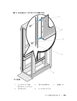
Страница 15: ...Rack Installation Guide 13 Figure 1 4 Marking the Vertical Rails 1 tape on vertical rails 1 ...

Страница 16: ...le which is located 4 U spaces below the upper marks or tape you placed on the vertical rail see Figure 1 5 3 Next push down on the mounting bracket flange until the mounting tabs seat in the square holes and the push button pops out and clicks see Figure 1 5 4 At the back of the cabinet pull back on the mounting bracket flange until the mounting tabs are in the appropriate holes and then push dow...

Страница 17: ...nstallation Guide 15 Figure 1 5 Installing the RapidRails Assemblies 1 upper mounting tab 2 push button 3 lower mounting tab 4 rail assembly mounting bracket flange 5 rail assemblies 2 1 front of rack 5 4 2 3 ...

Страница 18: ...upper mounting screw should be installed in the middle round hole of the 6th U space counting up from the bottom of the 10 U space The lower mounting screw should be installed in the middle round hole of the 1st U space counting up from the bottom NOTE The two midsection round holes on the VersaRails are for securing your system to the rack To assemble the VersaRails use only the round holes indic...

Страница 19: ...ation Guide 17 Figure 1 6 Installing the VersaRails Rail Assemblies 1 rail assembly mounting bracket flange 2 tooled arrow cutouts 2 3 vertical rails 4 Phillips screws 2 5 rail assemblies 2 1 front of rack 3 4 5 2 ...

Страница 20: ...on the front of the system as this part is fragile See Figure 1 7 NOTE If you are transporting a system that is already installed in the rack ensure that the two rack stabilizer mounting brackets are in place Locate the lower clinch nut holes on either side of the rack just below the default position for the strain relief bar To identify the default position of the strain relief bar and the attach...

Страница 21: ...Rack Installation Guide 19 Figure 1 7 Installing the System in the Rack 1 thumbscrews 4 2 LCD module 3 rail assemblies 2 3 2 1 ...

Страница 22: ...cables from the top of the rack install each strain relief bar in the default position for all systems except the lowest system in the rack Install the strain relief bar that ships with that system in one of the U spaces at the top of the rack to provide cable management by routing from above the installed systems If you are installing systems and routing cables only from the bottom of the rack al...

Страница 23: ...the Strain Relief Bar 1 cage nut 2 2 mounting screw 2 3 optional strain relief bar for upward cabling 4 default strain relief bar position 5 rack stabilizer shipping bracket 6 rack stabilizer shipping bracket lower clinch nut 1 3 2 back of rack 6 5 4 ...

Страница 24: ... bar NOTE Figure 1 9 illustrates a fully loaded system configuration If you are managing large numbers of cables consider first identifying each cable group attaching the enumerators and then bundling each cable group with the Velcro tie wraps Using the I O Cable Enumerators 1 Locate the I O cable enumerators that are included with your system see Figure 1 1 and Figure 1 2 The purpose of the enume...

Страница 25: ...n also group and order each column of eight cables not shown Securing the Cables to the Strain Relief Bar 1 Locate the Velcro tie wraps that are included with your system see Figure 1 1 and Figure 1 2 2 Facing the back of the system position the tie wrap over the cable bundle as it connects with the strain relief bar see Figure 1 9 NOTE Depending on your system configuration there are a number of ...

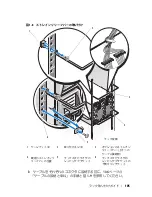
Страница 26: ...mentation provided with your rack cabinets This completes the rack installation of your system 1 I O cable enumerator segments 1 8 2 I O cable enumerator segments 9 16 3 cable notches 3 per segment 4 fiber optic cable connectors 16 5 fiber optic cables 16 6 strain relief bar 7 Velcro tie wraps 15 8 power cables 9 vertical rail 4 6 3 5 8 7 2 9 1 ...

Страница 27: ...eplacing 24 E enumerators cable 22 I I O cable enumerators 22 installing system in the rack 18 K kit contents RapidRails 9 VersaRails 10 M managing cables 20 marking the rack 11 18 R rack marking 11 18 rack mount precautions 7 rack requirements for VersaRails 7 rack stabilizer feet 8 RapidRails kit contents 9 routing cables 20 ...

Страница 28: ...26 Index S safety instructions 5 stabilizer feet 8 strain relief bar 23 installing 20 T tools and supplies four post kits 8 V VersaRails kit contents 10 ...

Страница 29: ...Guide d installation du rack ...

Страница 30: ...ans ce document peuvent être modifiées sans préavis 2007 Dell Inc Tous droits réservés La reproduction de ce document de quelque manière que ce soit sans l autorisation écrite de Dell Inc est strictement interdite Marques utilisées dans ce document Dell le logo DELL RapidRails et VersaRails sont des marques de Dell Inc Tous les autres noms de marques et marques commerciales utilisés dans ce docume...

Страница 31: ...du rack 34 Tâches d installation 34 Outils et fournitures recommandés 35 Contenu du kit RapidRails 35 Contenu du kit VersaRails 36 Retrait des portes du rack 37 Marquage du rack 37 Installation des assemblages RapidRails 40 Installation des assemblages VersaRails 42 Installation du système dans le rack 44 Acheminement et gestion des câbles de données 46 Installation de la barre de retenue 46 Branc...

Страница 32: ...30 Sommaire ...

Страница 33: ...onome installez d abord les pieds stabilisateurs avant et latéraux Pour plusieurs racks associés installez d abord les pieds stabilisateurs avant L installation de systèmes dans un rack non équipé de pieds stabilisateurs peut provoquer son basculement et entraîner des blessures Installez toujours les pieds stabilisateurs du rack avant d ajouter des composants dans celui ci Après avoir installé un ...

Страница 34: ...d aplomb et stable avant de tirer un composant hors de son compartiment Agissez avec précaution lorsque vous appuyez sur les loquets d éjection des rails pour insérer ou retirer un composant Veillez notamment à ne pas coincer vos doigts dans les assemblages de rails Ne surchargez pas le circuit d alimentation secteur du rack La consom mation totale du rack ne doit pas dépasser 80 de la capacité du...

Страница 35: ...longs ou trop abrupts sur lesquels l armoire pourrait vous échapper Ressortez les pieds réglables lorsque l armoire doit être soutenue ou pour lui éviter de glisser sur ses roulettes REMARQUE Pour plus d informations sur l installation du système proprement dit voir Installation du système dans le rack à la page 44 Informations importantes concernant la sécurité Respectez les précautions décrites ...

Страница 36: ...installation de systèmes dans un rack non équipé de pieds stabilisateurs peut provoquer son basculement et entraîner des blessures Installez toujours les pieds stabilisateurs du rack avant d ajouter des composants dans celui ci Les pieds stabilisateurs évitent au rack de basculer Consultez la documentation fournie avec le rack pour savoir comment installer et fixer les pieds stabilisateurs Tâches ...

Страница 37: ...ls Une barre de retenue Écrous à cage 2 Guides pour les câbles d E S 12 Attaches Velcro 15 Quatre vis à tête cruciforme 10 32 x 0 5 pouce REMARQUE Chaque kit de rack contient le nombre maximal d attaches Velcro et de guides pour câbles d E S dont vous auriez besoin pour un système totalement équipé Figure 1 1 Contenu du kit RapidRails 1 Assemblages RapidRails 2 Guides pour les câbles d E S 12 3 Ba...

Страница 38: ...taches Velcro et de guides pour câbles d E S dont vous auriez besoin pour un système totalement équipé REMARQUE Les vis non métriques sont identifiées dans ce document en fonction de leur taille et de leur nombre de filetages par pouce Par exemple une vis à tête cruciforme n 10 avec 32 filets par pouce est désignée par l appellation vis 10 32 Figure 1 2 Contenu du kit VersaRails 1 Assemblages Vers...

Страница 39: ... espace vertical de 10 U 44 45 cm ou 17 5 pouces pour chaque système installé dans le rack voir la figure 1 3 REMARQUE Il se peut que votre rack soit déjà marqué auquel cas cette procédure est inutile PRÉCAUTION Si vous installez plusieurs systèmes placez les assemblages de rails de façon que le premier système soit installé le plus bas possible dans le rack 1 Placez une marque sur les rails verti...

Страница 40: ...es au dessus de la marque que vous aviez faite à l origine ou remontez de 30 trous si vous utilisez un rack conforme aux normes CEA 310 E Si vous avez compté les trous placez la marque au dessus du trou supérieur Cette marque ou ce morceau de bande adhésive indique l emplacement du bord supérieur du système sur les rails verticaux voir la figure 1 4 1 U 44 mm 12 7 mm 15 9 mm 15 9 mm 12 7 mm ...

Страница 41: ...Guide d installation du rack 39 Figure 1 4 Marquage des rails verticaux 1 Bande apposée sur les rails verticaux 1 ...

Страница 42: ...nce de 4 U en dessous des marques ou du morceau de bande adhésive placées en haut du rail vertical voir la figure 1 5 3 Ensuite appuyez sur la collerette jusqu à ce que les pattes de montage s emboîtent dans les trous carrés et que le bouton poussoir ressorte avec un déclic voir la figure 1 5 4 À l arrière de l armoire tirez la collerette de montage vers l arrière jusqu à ce que les pattes s insèr...

Страница 43: ...du rack 41 Figure 1 5 Installation des assemblages RapidRails 1 Patte de montage supérieure 2 Bouton poussoir 3 Patte de montage inférieure 4 Collerette du support de montage 5 Assemblages de rails 2 1 Avant du rack 5 4 2 3 ...

Страница 44: ...oit être installée dans le trou rond situé au milieu de la sixième unité en remontant à partir du bas de l espace de 10 U La vis de montage inférieure doit être installée dans le trou rond situé au milieu de la première unité en remontant à partir du bas REMARQUE Les deux trous ronds situés au milieu des assemblages VersaRails doivent être utilisés pour fixer le système sur le rack Pour assembler ...

Страница 45: ...installation du rack 43 Figure 1 6 Installation des assemblages VersaRails 1 Collerette du support de montage 2 Découpes 2 3 Rails verticaux 4 Vis cruciformes 2 5 Assemblages de rails 2 1 Avant du rack 3 4 5 2 ...

Страница 46: ... s agit d une pièce fragile Voir la figure 1 7 REMARQUE Si vous transportez un système déjà installé dans le rack assurez vous que les deux supports de stabilisation du rack sont en place Repérez les trous inférieurs prévus pour les écrous rivets de chaque côté du rack juste en dessous de la position par défaut de la barre de retenue Pour identifier la position par défaut de la barre de retenue et...

Страница 47: ...Guide d installation du rack 45 Figure 1 7 Installation du système dans le rack 1 Vis moletées 4 2 Module LCD 3 Assemblages de rails 2 3 2 1 ...

Страница 48: ...à la position par défaut pour tous les systèmes sauf celui installé tout en bas du rack La barre de retenue livrée avec ce système doit être installée dans l un des espaces situés en haut du rack afin de permettre aux câbles d être acheminés au dessus des systèmes installés Si l installation des systèmes et l acheminement des câbles sont effectués uniquement à partir du bas du rack toutes les barr...

Страница 49: ... barre de retenue 1 Écrou à cage 2 2 Vis de montage 2 3 Barre de retenue en option pouracheminer les câbles vers le haut 4 Position par défaut de la barre de retenue 5 Support de stabilisation 6 Écrou rivet du support de stabilisation 1 3 2 Arrière du rack 6 5 4 ...

Страница 50: ...re de retenue REMARQUE La figure 1 9 présente un système totalement équipé Si vous gérez un nombre important de câbles il peut être préférable de commencer par identifier chaque groupe de câbles puis d installer les guide câbles et de regrouper chaque faisceau avec les attaches Velcro Utilisation des guides pour les câbles d E S 1 Munissez vous des guide câbles fournis avec le système voir la figu...

Страница 51: ...tient les huit câbles supérieurs des deux colonnes tandis que le second contient les huit câbles inférieurs Dans ce même exemple vous pourriez également grouper les huit câbles de chaque colonne dans un même guide câbles configuration non représentée Fixation des câbles sur la barre de retenue 1 Repérez les attaches Velcro fournies avec le système voir la figure 1 1 et la figure 1 2 2 Après vous ê...

Страница 52: ...uide de mise en route pour savoir comment installer un clip de fixation supplémentaire qui permet également d éviter une tension excessive des câbles d alimentation Figure 1 9 Fixation des câbles au rack 1 Guide câbles segments 1 8 2 Guide câbles segments 9 16 3 Encoches 3 par segment 4 Connecteurs pour câbles à fibre optique 16 5 Câbles à fibre optique 16 6 Barre de retenue 7 Attaches Velcro 15 8...

Страница 53: ...tion du rack 51 Réinstallation des portes du rack Consultez les procédures de réinstallation des portes figurant dans la documen tation fournie avec vos armoires rack L installation du système dans le rack est terminée ...

Страница 54: ...52 Guide d installation du rack ...

Страница 55: ...n 46 Regroupement 48 Consignes de sécurité 31 Contenu du kit RapidRails 35 VersaRails 36 G Gestion des câbles 46 Guide câbles 48 Câble 48 I Installation Rack système 44 M Marquage du rack 37 44 O Outils et fournitures Kit pour armoire à quatre montants 35 P Pieds stabilisateurs 34 Portes Réinstallation 51 Retrait 37 Précautions relatives au montage en rack 33 ...

Страница 56: ...54 Index R Rack Marquage 37 44 Rack pieds stabilisateurs 34 RapidRails contenu du kit 35 S Spécifications de rack requises pour les rails VersaRails 34 V VersaRails Contenu du kit 36 ...

Страница 57: ...Rack Installations anleitung ...

Страница 58: ...zum Tod führen könnte ____________________ Irrtümer und technische Änderungen vorbehalten 2007 Dell Inc Alle Rechte vorbehalten Die Reproduktion dieses Dokuments in jeglicher Form ohne vorherige schriftliche Genehmigung von Dell Inc ist streng verboten In diesem Text verwendete Marken Dell das DELL Logo RapidRails und VersaRails sind Marken von Dell Inc Alle anderen in dieser Dokumentation genannt...

Страница 59: ...n 62 Empfohlene Werkzeuge und Zubehör 63 Inhalt des RapidRails Rack Kits 63 Inhalt des VersaRails Rack Kits 64 Abnehmen der Rack Türen 65 Markieren des Racks 65 Installation der RapidRails Gleitschienen 68 Installation der VersaRails Gleitschienen 70 Installation des Systems im Rack 72 Verlegen und Verwalten von Kabeln 74 Installation der Zugentlastungsstrebe 74 Anschließen und Verlegen der Kabel ...

Страница 60: ...58 Inhalt ...

Страница 61: ... frei stehenden Racks die vorderen und seitlichen Stabilisatoren und bei Racks die mit anderen Racks verbunden sind die vorderen Stabilisatoren Wenn vor dem Einsetzen von Systemen in einem Rack keine Stabilisatoren angebracht werden kann das Rack unter Umständen umkippen und Verletzungen verursachen Befestigen Sie daher immer zuerst die Stabilisatoren bevor Sie Komponenten im Rack installieren Zie...

Страница 62: ...Stabilisatoren an mehreren miteinander verbundenen Racks die vordere Stabilisatoren bevor Sie Arbeiten am Rack durchführen Bestücken Sie das Rack immer von unten nach oben und setzen Sie die schwerste Komponente zuerst ein Vergewissern Sie sich dass das Rack gerade und stabil steht bevor Sie eine Komponente aus dem Rack ziehen Es besteht Quetschgefahr für die Finger wenn Sie auf die Schienen verri...

Страница 63: ...größter Vorsicht Fahren Sie die höhenverstellbaren Füße ein bevor Sie ein Rack bewegen Vermeiden Sie lange bzw steile Neigungen oder Rampen auf denen Sie die Kontrolle über das Rack verlieren könnten Fahren Sie die höhenverstellbaren Füße aus damit das Rack abgestützt wird und nicht wegrollen kann ANMERKUNG Wie das System selbst installiert wird erfahren Sie unter Installation des Systems im Rack ...

Страница 64: ...em Einsetzen von Systemen in einem Rack keine Stabilisatoren angebracht werden kann das Rack unter Umständen umkippen und Verletzungen verursachen Befestigen Sie daher immer zuerst die Stabilisatoren bevor Sie Komponenten im Rack installieren Die Stabilisatoren verhindern das Umkippen des Racks Anweisungen zur Installation und Befestigung der Stabilisatoren finden Sie in der Dokumentation zum Rack...

Страница 65: ...ails Gleitschienen Eine Zugentlastungsstrebe Käfigmuttern 2 E A Kabelzähler 12 Lösbare Kabelbinder 15 Vier Kreuzschlitzbundschrauben 10 32 x 0 5 Zoll ANMERKUNG Jedes Rack Kit enthält die maximale Anzahl Kabelbinder und E A Kabelzähler die für ein vollständig belegtes System benötigt werden Abbildung 1 1 Inhalt des RapidRails Rack Kits 1 RapidRails Gleitschienen 2 E A Kabelzähler 12 3 Zugentlastung...

Страница 66: ...male Anzahl Kabelbinder und E A Kabelzähler die für ein vollständig belegtes System benötigt werden ANMERKUNG Nichtmetrische Schrauben sind in diesem Dokument durch Größe und Zahl der Windungen pro Zoll gekennzeichnet So wird z B eine Kreuzschlitzschraube Nr 10 mit 32 Windungen pro Zoll als 10 32 Schraube bezeichnet Abbildung 1 2 Inhalt des VersaRails Rack Kits 1 VersaRails Gleitschienen 2 E A Kab...

Страница 67: ...stand siehe Abbildung 1 3 ANMERKUNG Möglicherweise ist das Rack bereits markiert in diesem Fall ist kein weiteres Markieren erforderlich VORSICHT Wenn Sie mehr als ein System installieren montieren Sie die Gleitschienen so dass das erste System in die unterste mögliche Position im Rack zu liegen kommt 1 Bringen Sie auf den vorderen vertikalen Schienen des Racks eine Markierung an der Stelle an an ...

Страница 68: ...oberhalb Ihrer ursprünglichen Markierung oder zählen Sie bei Racks nach CEA 310 E Standard 30 Löcher nach oben Wenn Sie Löcher gezählt haben machen Sie eine Markierung direkt über dem obersten Loch Die Markierung bzw das Kreppband zeigt die spätere Position der Oberkante des Systems an den vertikalen Schienen siehe Abbildung 1 4 1 U 44 mm 12 7 mm 15 9 mm 15 9 mm 12 7 mm ...

Страница 69: ...Rack Installationsanleitung 67 Abbildung 1 4 Vertikale Schienen markieren 1 Kreppband auf vertikalen Schienen 1 ...

Страница 70: ... unterhalb der oberen Markierungen an der vertikalen Schiene einrastet siehe Abbildung 1 5 3 Drücken Sie danach auf den Flansch der Montagehalterung bis die Montagehaken in den Rechtecklöchern sitzen und der Verriegelungsknopf einrastet siehe Abbildung 1 5 4 Ziehen Sie an der Rückseite des Rack Gestellschranks den Flansch der Montagehalterung nach hinten bis die Montagehaken in die entsprechenden ...

Страница 71: ...ionsanleitung 69 Abbildung 1 5 RapidRails Gleitschienen installieren 1 Oberer Montagehaken 2 Drucktaste 3 Unterer Montagehaken 4 Montagehalterungsflansch der Gleitschienen 5 Gleitschienen 2 1 Rack Vorderseite 5 4 2 3 ...

Страница 72: ...ldung 1 6 Die obere Montageschraube sollte im mittleren Rundloch der sechsten U Einheit eingesetzt werden wobei von der Unterseite des 10 U Bereichs gezählt wird Die untere Montageschraube sollte im mittleren Rundloch der ersten U Einheit eingesetzt werden von der Unterseite an gezählt ANMERKUNG Die zwei Rundlöcher im mittleren Bereich der VersaRails sichern das System im Rack Um die VersaRails zu...

Страница 73: ...g 71 Abbildung 1 6 VersaRails Schiebeeinheiten installieren 1 Montagehalterungs flansch der Gleitschienen 2 Pfeilförmige Aussparungen 2 3 Vertikale Schienen 4 Kreuzschlitzschrauben 2 5 Gleitschienen 2 1 Rack Vorderseite 3 4 5 2 ...

Страница 74: ...eil empfindlich ist Siehe Abbildung 1 7 ANMERKUNG Wenn Sie ein System transportieren das bereits im Rack installiert ist stellen Sie sicher dass die zwei Stabilisatorwinkel angebracht sind Machen Sie die unteren Klemmmutterlöcher auf beiden Seiten des Racks direkt unter der Standardposition für die Zugentlastungsstrebe ausfindig Die Standardposition für die Zugentlastungsstrebe und die Befestigung...

Страница 75: ...Rack Installationsanleitung 73 Abbildung 1 7 System im Rack installieren 1 Rändelschrauben 4 2 LCD Modul 3 Gleitschienen 2 3 2 1 ...

Страница 76: ... 9 Installation der Zugentlastungsstrebe ANMERKUNG Dell empfiehlt die Zugentlastungsstrebe auf der Rückseite des Systems zu installieren und die lösbaren Kabelbinder zu verwenden um die Kabel zu verwalten und bei allen Kabelkonfigurationen eine bestmögliche Zugentlastung zu gewährleisten ANMERKUNG Wenn Sie Systeme in einem Rack installieren und Kabel von der Oberseite des Racks verlegen installier...

Страница 77: ...osition über dem System installieren müssen Sie an jedem Befestigungs punkt zwei entsprechende Käfigmuttern auf der Rückseite der Schiene befestigen siehe Abbildung 1 8 2 Machen Sie auf der Rückseite des Systems auf der linken und rechten vertikalen Schiene die dritte U Einheit ausfindig gezählt vom unteren Rand des Systems aus Jede U Einheit umfasst drei Löcher Installieren Sie die Zugentlastungs...

Страница 78: ...tlastungsstrebe 1 Käfigmuttern 2 2 Befestigungs schrauben 2 3 Optionale Zugentlastungs strebe für oberseitige Verkabelung 4 Standardposition für Zugentlastungsstrebe 5 Rack Stabilisator winkel 6 Untere Klemmmutter für Rack Stabilisatorwinkel 1 3 2 Rack Rückseite 6 5 4 ...

Страница 79: ...isieren ANMERKUNG Abbildung 1 9 zeigt eine vollständige Systemkonfiguration Wenn Sie eine große Zahl von Kabeln verwalten sollten Sie zunächst jede Kabelgruppe identifizieren die Kabelzähler anbringen und danach die einzelnen Kabelgruppen mit den Kabelbindern bündeln Verwenden der E A Kabelzähler 1 Die E A Kabelzähler sind im Lieferumfang des Systems enthalten siehe Abbildung 1 1 und Abbildung 1 2...

Страница 80: ...ls acht Kabel gruppiert und an einem Zähler befestigt sind Abbildung 1 9 zeigt 16 Kabel die mit zwei Zählern gruppiert und geordnet sind einer mit den oberen acht Kabeln von beiden Kolonnen und der andere mit den unteren acht Kabeln von beiden Kolonnen Beim gleichen Beispiel können Sie auch jede Kolonne von acht Kabeln gruppieren und ordnen nicht dargestellt Sichern der Kabel an der Zugentlastungs...

Страница 81: ...h Kabelbündel leicht von E A Modulen wegbewegen lassen um diese zu entfernen oder zu installieren ANMERKUNG Stellen Sie sicher dass Sie alle Netzstromkabel von beiden Seiten des Systems mit Kabelbindern an der Zugentlastungsstrebe sichern wie in Abbildung 1 9 gezeigt Anweisungen zum Anbringen der Netzstromka belhalteklemme die für zusätzliche Zugentlastung sorgt erhalten Sie im Handbuch zum Einsti...

Страница 82: ...ck sichern 1 E A Kabelzähler Segmente 1 8 2 E A Kabelzähler Segmente 9 16 3 Kabelrasten 3 pro Segment 4 Stecker von Glasfaserkabeln 16 5 Glasfaserkabel 16 6 Zugentlastungs strebe 7 Lösbare Kabelbinder 15 8 Netzstromkabel 9 Vertikale Schiene 4 6 3 5 8 7 2 9 1 ...

Страница 83: ...Installationsanleitung 81 Wiederanbringen der Rack Türen Siehe Vorgehensweise zum Anbringen der Türen in der Dokumentation zum Rack Gestellschrank Damit ist die Installation des Systems im Rack abgeschlossen ...

Страница 84: ...82 Rack Installationsanleitung ...

Страница 85: ...n 77 Sichern 78 Verbindungen 77 Verlegen 74 Verwalten 74 Zugentlastungsstrebe 78 Kabel verlegen 74 Kabel verwalten 74 Kit Inhalt RapidRails 63 VersaRails 64 M Markieren des Racks 65 72 R Rack Markieren 65 72 Rack Anforderungen für VersaRails 62 Rack Stabilisatoren 62 S Sicherheitshinweise 59 Stabilisatoren 62 T Türen Einsetzen 81 Entfernen 65 ...

Страница 86: ...84 Stichwortverzeichnis V VersaRails Kit Inhalt 64 Vorsichtsmaßnahmen bei der Rack Montage 61 W Werkzeuge und Zubehör Vier Stützen Kits 63 Z Zähler Kabel 77 Zugentlastungsstrebe 78 Installation 74 ...

Страница 87: ...ラック取り付けガイド ...

Страница 88: ...なる可能性が あることを示しています ____________________ 本書の内容は予告なく変更されることがあります 2007 すべての著作権は Dell Inc にあります Dell Inc の書面による許可のない複製は いかなる形態においても厳重に禁じられ ています 本書に使用されている商標 Dell DELL ロゴ RapidRails および VersaRails は Dell Inc の商標です 本書では 必要に応じて上記以外の商標や会社名が使用されている場合がありますが それらの商標や会社名は 一切 Dell Inc に帰属するものではありません 2007 年 8 月 P N DX845 Rev A00 ...

Страница 89: ...安全に関する重要な注意 92 VersaRails のラック要件 92 ラックスタビライザ 92 取り付け手順 93 推奨する工具および備品 93 RapidRails ラックキットの内容 93 VersaRails ラックキットの内容 94 ラック扉の取り外し 95 ラックへの印付け 96 RapidRails アセンブリの取り付け 98 VersaRails アセンブリの取り付け 100 ラックへのシステムの取り付け 102 ケーブルの配線と管理 104 ストレインリリーフバーの取り付け 104 ケーブルの接続と束ね 106 ラック扉の取り付け 109 索引 111 ...

Страница 90: ...88 目次 ...

Страница 91: ...に システムも 含まれます 警告 単体ラックでは前面と側面のスタビライザ 連結ラックでは前面 のスタビライザを取り付けてからラックにシステムを取り付けてくだ さい スタビライザを正しく取り付けずにシステムをラックに取り付け ると ラックが転倒し けがをするおそれがあります 必ずスタビライザ を取り付けてから ラックにコンポーネントを取り付けてください ラックにシステム コンポーネントを取り付けた後は 一度に複数のコン ポーネントをラックのスライドアセンブリを使って引き出さないでくだ さい 重みでラックが転倒し 大けがをするおそれがあります メモ お使いのシステムは 独立型のユニットとして また カスタ マーラックキットで構成される Dell ラックキャビネットに取り付けるコ ンポーネントとして その安全性が保証されています それ以外のラック キャビネットにシステムおよびラックキットを取り付...

Страница 92: ... に伸び ラックの全重量が床面にかかっていることを確認してくだ さい ラックで作業をする前に ラックが 1 つの場合は前面と側面 のスタビライザ 複数のラックを連結する場合は前面のスタビライ ザを取り付けます ラックには必ず下から上へと 最も重いものから順に設置してくだ さい コンポーネントをラックから引き出す前に ラックが水平で安定し ていることを確認してください レールリリースラッチを押してコンポーネントをラックから出し入 れするときは スライドレールに指をはさまれないように注意して ください ラックに電力を送る AC 分岐回路に過重電流を流さないでください ラックの総負荷が分岐回路定格の 80 パーセントを超えないようにし てください ラック内のコンポーネントが十分に通気されることを確認してくだ さい ラックに取り付けたコンポーネントの作業中に 他のコンポーネン トの上に乗ったり 足...

Страница 93: ...つ必要です 作業を開始する前に システムをラックに取り付ける作業を始める前に 89 ページの 安全に お使いいただくための注意 と 製品情報ガイド に記載された安全に 関する注意をよく読んでください 警告 複数のシステムをラックに取り付ける場合は 1 台のシステムの取 り付け手順を完了してから 次のシステムの取り付けに進んでください 警告 ラックキャビネットはサイズが非常に大きく重量もありますが キャスターで簡単に移動できるようになっています このキャスターには ブレーキがないため ラックキャビネットを移動するときは十分な注意が 必要です ラックキャビネットを別の場所に移動するときは 水平調節用 の脚を収納してください 長い傾斜面 急勾配のある場所 スロープ など バランスが取りにくい場所にはキャビネットを設置しないでくだ さい 水平調節用の脚を伸ばしてキャビネットを支え キャビネットが動...

Страница 94: ...ム用のラックキットを使用すると システムが損 傷し ご自身や周囲の人々がけがをするおそれがあります VersaRails のラック要件 注意 VersaRails ラックキットは 全米家電協会 CEA 規格 CEA 310 E 国際電気標準会議 IEC 297 ドイツ協業規格 DIN 41494 の仕様を満たす ラックに トレーニングを受けたサービス技術者が取り付けるように設計 されています ラックキットは ラックに取り付けるシステム 1 台につき 1 セットずつ必要です ラックスタビライザ 警告 単体ラックでは前面と側面のスタビライザ 連結ラックでは前面 のスタビライザを取り付けてからラックにシステムを取り付けてくだ さい スタビライザを正しく取り付けずにシステムをラックに取り付け ると ラックが転倒し けがをするおそれがあります 必ずスタビライザ を取り付けてから ラックにコンポーネン...

Страница 95: ...ーブルの配線と管理 ストレインリリーフバーの取り付け I O ケーブル連番クリップの使用 6 ラック扉の取り付け 推奨する工具および備品 2 プラスドライバ マスキングテープまたはフェルトペン 取り付け穴に印を付けると きに使用 定規または巻尺 RapidRails ラックキットの内容 RapidRails ラックキットには 以下の部品が含まれています 図 1 1 を参照 RapidRails アセンブリ 1 対 ストレインリリーフバー 1 ケージナット 2 I O ケーブル連番クリップ 12 ベルクロタイラップ 15 10 32 x 0 5 インチフランジヘッドプラスネジ 4 メモ どのラックキットにも 完全装備時のシステムに必要な最大数の ベルクロタイラップと I O ケーブル連番クリップが含まれています ...

Страница 96: ...I O ケーブル連番クリップ 12 ベルクロタイラップ 15 10 32 x 0 5 インチフランジヘッドプラスネジ 12 メモ どのラックキットにも 完全装備時のシステムに必要な最大数の ベルクロタイラップと I O ケーブル連番クリップが含まれています メモ 本書では メートル法規格外のネジはサイズとインチ当たり のネジ山数で表記されています たとえば 1 インチに 32 本のネジ山が ある 10 プラスネジは 10 32 ネジと表記します 1 RapidRails アセンブリ 2 I O ケーブル連番ク リップ 12 3 ストレインリリー フバー 4 ベルクロタイ ラップ 15 5 フランジヘッド 10 32 x 0 5 インチ プラスネジ 4 6 ケージナット 2 3 1 2 4 6 5 ...

Страница 97: ...トに付属のマニュアルに記載されている扉の取り外し手 順を参照してください 警告 ラックキャビネットの扉の大きさと重さを考慮して 取り付けお よび取り外しは 1 人では行わないでください 警告 取り外した扉は 不意に倒れてけがをしないような場所に保管し てください 1 VersaRails アセンブリ 2 I O ケーブル連番ク リップ 12 3 ストレインリリ ーフバー 4 ベルクロタ イラップ 15 5 フランジヘッド 10 32 x 0 5 インチ プラスネジ 12 6 クリップナット 2 3 1 2 4 6 5 ...

Страница 98: ...が付けられている場合は この手順は必要あり ません 警告 複数のシステムを取り付ける場合は ラックの最下段に 1 台目のシ ステムを取り付けられるように レールアセンブリを取り付けてください 1 ラックの前面垂直レール上で ラックキャビネットに取り付けるシ ステムの底部の位置を決め 印を付けます 底部にあたる各 1 U スペースの位置は 穴と穴の間が狭い方の金属 部分の中央です 横線で印が付いているラックキャビネットもあり ます 図 1 3 を参照 図 1 3 1 ラックユニット 1 U 1 U 44 mm 12 7 mm 15 9 mm 15 9 mm 12 7 mm ...

Страница 99: ...イド 97 2 ラックの前部垂直レールに 最初に印を付けた場所から約 44 45 cm 上 CEA 310 E 規格に適合したラックであれば 30 個上の穴 にフェ ルトペンやマスキングテープで印を付けます 穴の数で測った場合は 一番上の穴の真上に印を付けます 垂直レール上のこのマークまた はテープが システムの上端の位置を示します 図 1 4 を参照 図 1 4 垂直レールの印付け 1 垂直レールに貼ったテープ 1 ...

Страница 100: ...て 10 番目の穴 に差し込みます 図 1 5 を参照 2 レールアセンブリを正面に向かって押し 垂直レールに付けた上の 印またはテープの 4 U スペース下の角型の穴に上部取り付けタブを 差し込みます 図 1 5 を参照 3 次に 2 つの取り付けタブが両方とも角型の穴に入り 押しボタンが カチッという音がして飛び出すまで 取り付けブラケットのフラン ジを下に押します 図 1 5 を参照 4 キャビネットの背面で 取り付けブラケットのフランジを後ろに引 いて 取り付けタブを対応する穴に差し込み フランジを下に押し て取り付けタブを角型の穴に固定します 完全に固定されるとプッ シュボタンがカチッと飛び出します 5 ラックの反対側のレールアセンブリで 手順 1 手順 4 を繰り返し ます メモ 左右の垂直レールで 取り付け用レールが同じ高さに取り付 けられていることを確認します ...

Страница 101: ...ラック取り付けガイド 99 図 1 5 RapidRails アセンブリの取り付け 1 上部取り付けタブ 2 押しボタン 3 下部取り付けタブ 4 レールアセンブリ取り 付けブラケットフランジ 5 レールアセンブリ 2 1 ラック正面 5 4 2 3 ...

Страница 102: ... 0 5 インチフランジヘッドプラスネジを前面取り付け フランジに取り付け レールアセンブリを前面垂直レールに固定し ます 図 1 6 を参照してください 上部取り付けネジは 10 U スペースの一番下から数えて 6 U 6 番目の U スペースの中央の穴に取り付けます 下部取り付けネジは 一番下から数えて 1 U 最初の U スペースの中央の穴に取り付けます メモ VersaRails 上の中央部分にある 2 つの丸穴は システムをラック に固定するためのものです VersaRails の組み立てには 2 つの切り欠 きの矢印によって指し示されている丸穴のみを使用してください 図 1 6 を参照 4 キャビネットの背面から 取り付けブラケットフランジを後ろに引 いて 取り付け穴を背面垂直レールのそれぞれ対応する穴に合わせ ます 5 2 本の 10 32 x 0 5 インチフランジヘッドプ...

Страница 103: ...ラック取り付けガイド 101 図 1 6 VersaRails レールアセンブリの取り付け 1 レールアセンブリ取り 付けブラケットフランジ 2 切り欠きの矢印 2 3 垂直レール 4 プラスネジ 2 5 レールアセンブリ 2 1 ラック正面 3 4 5 2 ...

Страница 104: ...ステム前面の LCD モジュールは壊れやすいため システムを持 ち上げてラックに取り付ける際に その部分を持たないでください 図 1 7 を参照してください メモ ラックに取り付け済みのシステムを移動する場合は 2 つのラック スタビライザ取り付けブラケットが所定の位置にあることを確認してくだ さい ストレインリリーフバー用の既定位置のすぐ下にあるラック側面のク リンチナット穴 下側 を確認します ストレインリリーフバーの既定位置とスタビライザ取り付けブラケッ ト用の取り付け穴を確認するには 図 1 8 を参照してください 1 システムをラックに取り付ける前に ブレード 背面モジュール 電源ユニット ファンのすべてを取り外します 2 システムをラックに取り付ける位置まで持ち上げます システムを持ち上げるときは 3 人以上で作業することをお勧めし ます 3 システムをラック内に移動し レール...

Страница 105: ...ラック取り付けガイド 103 図 1 7 ラックへのシステムの取り付け 1 蝶ネジ 4 2 LCD モジュール 3 レールアセンブリ 2 3 2 1 ...

Страница 106: ...お勧めします メモ ラックにシステムを取り付け ラックの一番上からケーブルを配 線する場合は ラック内の一番下のシステムを除くすべてのシステムで 既定位置にストレインリリーフバーを取り付けます システムに付属のス トレインリリーフバーをラック上部の U スペースのいずれかに取り付け 取り付けたシステムの上から配線することでケーブルを管理します システムの取り付けとケーブルの配線をラックの一番下からのみ行う場合 は すべてのストレインリリーフバーをそれぞれの既定位置に取り付ける 必要があります システム上下のケーブル配線の例は 図 1 8 および 図 1 9 を参照してください 1 システムにすべてのケーブルを接続する前に システムに付属のス トレインリリーフバー および対応する取り付けネジを確認してく ださい 図 1 1 および 図 1 2 を参照 メモ システムより上の任意の位置にストレ...

Страница 107: ...リーフバーの取り付け 3 ケーブルをそれぞれのコネクタに接続する前に 106 ページの ケーブルの接続と束ね の手順と 図 1 9 を参照してください 1 ケージナット 2 2 取り付けネジ 2 3 オプションのストレイン リリーフバー 上方への ケーブル接続用 4 既定のストレインリ リーフバーの位置 5 ラックスタビライザの シッピングブラケット 6 ラックスタビライザの シッピングブラケットの 下側クリンチナット 1 3 2 ラック背面 6 5 4 ...

Страница 108: ...きます メモ 完全装備のシステム構成を 図 1 9 に示します 管理するケー ブルの本数が多い場合は 最初に各ケーブルグループを確認し 連 番クリップを取り付け ベルクロタイラップを使用して各ケーブル グループを束ねることをお勧めします I O ケーブル連番クリップの使用 1 システムに付属の I O ケーブル連番クリップを確認します 図 1 1 および 図 1 2 を参照 連番クリップの目的は ケーブルコネクタと その各ケーブルの順序をそのままの状態に保ち システムモジュー ルの取り外しと交換を容易にすることです 2 ケーブル 8 本から成る各グループについては 1 および 8 と刻印さ れた側を選びます ケーブル 16 本から成るグループについては 1 および 8 と刻印された連番クリップと 9 および 16 と刻印された 連番クリップの計 2 つが必要です 図 1 9 を参照 メモ ...

Страница 109: ...1 つは両方の縦列からの下側 8 本のケーブルを留めてい ます これと同じ例で 8 本のケーブルから成る各縦列をグルー プ化し 整理することもできます 図には示してありません ケーブルをストレインリリーフバーに固定する方法 1 システムに付属のベルクロタイラップを確認します 図 1 1 および 図 1 2 を参照 2 システムの背面に回って タイラップをケーブルの束に巻きつけ ストレインリリーフバーに固定します 図 1 9 を参照 メモ システム構成に応じて ベルクロタイラップを使用してケー ブルの束をストレインリリーフバーに固定するケーブルのまとめ方 はさまざまです 3 ケーブルをバーに固定するには タイラップをバーの背面に通し 次にケーブルの束に再び巻きつけ タイラップをケーブルの前でク ロスさせて ケーブルの束をまとめます 図 1 9 を参照 4 ケーブルの束がばらばらにならないよう...

Страница 110: ...取り付けガイド 図 1 9 ラックへのケーブルの固定 1 I O ケーブル連番クリッ プ セグメント 1 8 2 I O ケーブル連番ク リップ セグメン ト 9 16 3 切り込み 各セグメ ントに 3 種類 4 光ファイバーケーブル コネクタ 16 5 光ファイバーケー ブル 16 6 ストレインリリーフ バー 7 ベルクロタイラップ 15 8 電源ケーブル 9 垂直レール 4 6 3 5 8 7 2 9 1 ...

Страница 111: ...ラック取り付けガイド 109 ラック扉の取り付け ラックキャビネットに付属のマニュアルに記載されている扉の取り付け手 順を参照してください これでラックへのシステムの取り付けは完了です ...

Страница 112: ...110 ラック取り付けガイド ...

Страница 113: ...内容 93 V VersaRails キットの内容 94 95 VersaRails のラック要件 92 あ 安全にお使いいただくた めの注意 89 き キットの内容 RapidRails 93 VersaRails 95 け ケーブル 管理 104 固定 107 ストレインリリーフバー 107 接続 106 束ね 106 配線 104 ケーブルの管理 104 ケーブルの配線 104 こ 工具と備品 4 柱型キット 93 す スタビライザ 92 ストレインリリーフバー 107 取り付け 104 ...

Страница 114: ...112 索引 と 扉 取り外し 95 取り付け 109 取り付け システムをラックへ 102 ら ラック 印付け 96 102 ラックスタビライザ 92 ラック取り付け時の注 意事項 91 ラックへの印付け 96 102 れ 連番クリップ ケーブル 106 ...

Страница 115: ...Guía de instalación del rack ...

Страница 116: ...dificarse sin previo aviso 2007 Dell Inc Todos los derechos reservados Queda estrictamente prohibida la reproducción de este documento en cualquier forma sin la autorización por escrito de Dell Inc Marcas comerciales utilizadas en este texto Dell el logotipo de DELL RapidRails y VersaRails son marcas comerciales de Dell Inc Otras marcas y otros nombres comerciales pueden utilizarse en este documen...

Страница 117: ...alación 120 Herramientas y material recomendados 120 Contenido del kit de rack RapidRails 121 Contenido del kit de rack VersaRails 122 Extracción de las puertas del rack 123 Marcado del rack 123 Montaje de los ensamblajes RapidRails 126 Instalación de los ensamblajes VersaRails 128 Instalación del sistema en el rack 130 Colocación y tendido de cables 132 Instalación de la barra liberadora de tensi...

Страница 118: ...116 Contenido ...

Страница 119: ...s frontales y laterales para racks individuales o bien los estabilizadores frontales para varios racks unidos Si no se instalan estabilizadores antes de realizar el montaje de los sistemas el rack puede volcarse y ello puede producir lesiones personales Por lo tanto instale siempre los estabilizadores antes de instalar los componentes en el rack Una vez que haya instalado el sistema o los componen...

Страница 120: ...ga cuidado al presionar los pestillos de liberación de los rieles de componentes y al extraer o introducir un componente del rack puesto que sus dedos pueden quedar aprisionados en los rieles deslizantes No sobrecargue el circuito de alimentación de CA que suministra energía al rack La carga total del rack no debe ser superior al 80 por ciento de la corriente nominal del circuito Los componentes d...

Страница 121: ...sistema en el rack en la página 130 Información de seguridad importante Cuando instale el sistema en el rack tenga en cuenta las precauciones de seguridad que se indican en los apartados siguientes PRECAUCIÓN debe seguir estrictamente los procedimientos que se explican en este documento para protegerse a sí mismo y a otras personas que puedan verse involucradas El sistema puede tener un tamaño y u...

Страница 122: ...io rack para obtener instrucciones sobre la instalación y la fijación de los pies estabilizadores Tareas de instalación La instalación de un kit de rack implica realizar las tareas siguientes en el orden indicado 1 Extracción de las puertas del rack 2 Marcado del rack en caso necesario 3 Instalación de los ensamblajes de rieles en el rack Instalación de RapidRails Instalación de VersaRails 4 Insta...

Страница 123: ... 15 Cuatro tornillos Phillips con arandela 10 32 x 0 5 pulgadas NOTA cada kit de rack contiene el número máximo de abrazaderas de velcro y de enumeradores para cables de E S necesarios para contar con un sistema cargado por completo Figura 1 1 Contenido del kit de rack RapidRails 1 Ensamblajes RapidRails 2 Enumeradores para cables de E S 12 3 Barra liberadora de tensión 4 Abrazaderas de velcro 15 ...

Страница 124: ... de abrazaderas de velcro y de enumeradores para cables de E S necesarios para contar con un sistema cargado por completo NOTA en este documento los tornillos no métricos se identifican por el tamaño y el número de roscas por pulgada Por ejemplo un tornillo Phillips del n º 10 con 32 roscas por pulgada se identifica como un tornillo 10 32 Figura 1 2 Contenido del kit de rack VersaRails 1 Ensamblaj...

Страница 125: ...45 cm de espacio vertical para cada sistema que monte en el rack vea la figura 1 3 NOTA en caso de que el rack ya esté marcado no es necesario realizar este procedimiento PRECAUCIÓN si va a instalar más de un sistema instale los ensamblajes de rieles de modo que el primer sistema quede instalado en la posición más baja disponible en el rack 1 Coloque una marca en los rieles verticales frontales en...

Страница 126: ...va aproximadamente 44 45 cm por encima de la marca original o cuente 30 orificios en un rack que cumpla los estándares CEA 310 E Si ha contado orificios realice una marca justo por encima del orificio superior Esta marca o trozo de cinta indica dónde se va a situar el borde superior del sistema en los rieles verticales vea la figura 1 4 1 U 44 mm 12 7 mm 15 9 mm 15 9 mm 12 7 mm ...

Страница 127: ...Guía de instalación del rack 125 Figura 1 4 Marcado de los rieles verticales 1 Cinta en los rieles verticales 1 ...

Страница 128: ...jo de las marcas superiores o la cinta colocados en el riel vertical vea la figura 1 5 3 A continuación presione hacia abajo la superficie de montaje del soporte hasta que las lengüetas de montaje encajen en los orificios cuadrados y el pulsador se expulse y se oiga un clic vea la figura 1 5 4 En la parte posterior del armario tire hacia atrás de la superficie de montaje del soporte hasta que las ...

Страница 129: ...a 1 5 Instalación de los ensamblajes RapidRails 1 Lengüeta de montaje superior 2 Pulsador 3 Lengüeta de montaje inferior 4 Superficie de montaje del soporte del ensamblaje de rieles 5 Ensamblajes de rieles 2 1 Parte frontal del rack 5 4 2 3 ...

Страница 130: ...llo de montaje superior se debe instalar en el orificio redondo central del sexto espacio U contando desde la parte inferior del espacio 10 U El tornillo de montaje inferior se debe instalar en el orificio redondo central del primer espacio U contando desde la parte inferior NOTA los dos orificios redondos de la sección central del VersaRails sirven para fijar el sistema al rack Para ensamblar el ...

Страница 131: ...6 Montaje de los ensamblajes de rieles VersaRails 1 Superficie de montaje del soporte del ensamblaje de rieles 2 Recortes en forma de flecha 2 3 Rieles verticales 4 Tornillos Phillips 2 5 Ensamblajes de rieles 2 1 Parte frontal del rack 3 4 5 2 ...

Страница 132: ...instalado en el rack compruebe que los dos soportes de montaje estabilizadores del rack se encuentren en su lugar Localice los orificios inferiores para tuercas remachadas de ambos lados del rack situados justo debajo de la posición predeterminada para la barra liberadora de tensión Para identificar la posición predeterminada de la barra liberadora de tensión y los puntos de fijación de los soport...

Страница 133: ...Guía de instalación del rack 131 Figura 1 7 Instalación del sistema en el rack 1 Tornillos mariposa 4 2 Módulo LCD 3 Ensamblajes de rieles 2 3 2 1 ...

Страница 134: ...liberadora de tensión NOTA Dell recomienda instalar la barra liberadora de tensión en la parte posterior del sistema y utilizar las abrazaderas de velcro con esta barra para tender los cables y liberar al máximo la tensión de todas las configuraciones de cableado NOTA si va a instalar sistemas en un rack y a colocar los cables desde la parte superior del rack instale cada barra liberadora de tensi...

Страница 135: ...onal por encima del sistema necesitará dos tuercas prisioneras para instalarla en la parte posterior del riel en cada punto de fijación vea la figura 1 8 2 En la parte posterior del sistema en los rieles verticales izquierdo y derecho localice el tercer espacio U desde el extremo inferior del sistema Cada espacio U abarca tres orificios Instale la barra liberadora de tensión prede terminada en el ...

Страница 136: ...illo de montaje 2 3 Barra liberadora de tensión opcional para el cableado hacia arriba 4 Posición predeterminada de la barra liberadora de tensión 5 Soporte de transporte para estabilización del rack 6 Tuerca remachada inferior del soporte de transporte para estabilización del rack 1 3 2 Parte posterior del rack 6 5 4 ...

Страница 137: ...a cables de E S en la página 135 antes de utilizar las abrazaderas de velcro para fijar los grupos de cables a la barra liberadora de tensión NOTA en la figura 1 9 se muestra una configuración de sistema cargado por completo Si va a tender un gran número de cables pruebe a identificar primero cada grupo de cables colocar los enumeradores y unir cada grupo de cables mediante las abrazaderas de velc...

Страница 138: ... segmento y así sucesivamente Vea la figura 1 9 NOTA según la configuración del cableado puede agrupar y ordenar los cables de distintas maneras mientras no agrupe ni conecte más de ocho cables a cada enumerador En la figura 1 9 se muestran 16 cables agrupados y ordenados mediante dos enumeradores uno con los ocho cables superiores de ambas columnas y el otro con los ocho cables inferiores de amba...

Страница 139: ...n deslizarse en la barra liberadora de tensión Este paso garantiza que los grupos de cables se puedan mover con facilidad sin contacto con los módulos de E S durante la extracción y la instalación NOTA asegúrese de fijar todos los cables de alimentación tendidos desde ambos lados del sistema a la barra liberadora de tensión con las abrazaderas de velcro como se muestra en la figura 1 9 Consulte la...

Страница 140: ...les de E S segmentos 1 8 2 Enumerador para cables de E S segmentos 9 16 3 Muescas para cables 3 por segmento 4 Conectores de los cables de fibra óptica 16 5 Cables de fibra óptica 16 6 Barra liberadora de tensión 7 Abrazaderas de velcro 15 8 Cables de alimentación 9 Riel vertical 4 6 3 5 8 7 2 9 1 ...

Страница 141: ...ack 139 Colocación de las puertas del rack Para colocar las puertas consulte los procedimientos correspondientes en la documentación suministrada con los armarios rack Con esto se completa la instalación del rack en el sistema ...

Страница 142: ...140 Guía de instalación del rack ...

Страница 143: ... cables de E S enumeradores 135 colocar cables 132 contenido del kit RapidRails 121 VersaRails 122 E enumeradores cable 135 H herramientas y material kits de cuatro postes 120 I instalar sistema en el rack 130 instrucciones de seguridad 117 M marcar el rack 123 130 P pies estabilizadores 120 precauciones para el montaje del rack 119 puertas colocar 139 extraer 123 ...

Страница 144: ...142 Índice R rack marcar 123 130 rack pies estabilizadores 120 RapidRails contenido del kit 121 requisitos del rack para VersaRails 119 T tender cables 132 V VersaRails contenido del kit 122 ...

Отзывы: