4. Disassembly and Assembly Procedures
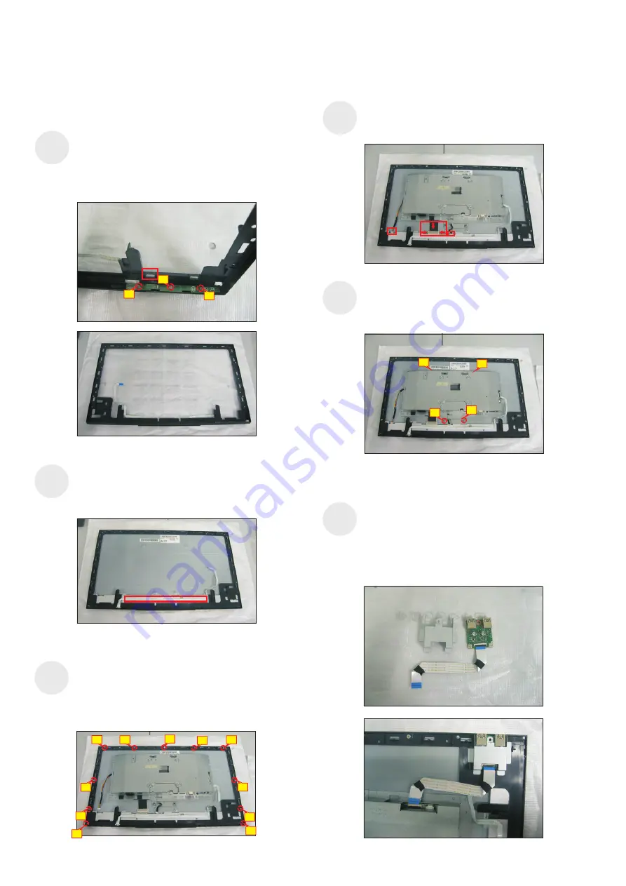
Take a function key board and a middle bezel, then
thread the function key cable through the hole of the
middle bezel, and then locate the function board unit
to the specific position of the middle bezel. U
function key board
middle bezel.
se a
Philips-head screwdriver to tighten three screws for
locking the
with the
(No.1~3 Screw size= M2x3.3, Torque=1
±0.2
kgfxcm)
S7
2
1
3
P
and push the middle bezel for two parts firmly
attachment. Tear off all the double-faced adhesive
tapes which pasted on the back of the function key
cable, and then fix the cable on the panel.
ut down the middle bezel on the assembled unit
S8
Adjust the bracket chassis module, and then u
.
se a
Philips-head screwdriver to tighten four screws for
locking the bracket chassis with the panel module
(No.1~4 Screw size= M3x4, Torque=5
±0.5
kgfxcm)
Use a Philips-head screwdriver to tighten nine
screws for locking the middle bezel with the
assembled unit. Use a Philips-head screwdriver to
tighten two screws for locking the front bezel. Put the
bracket chassis module on the panel module.
(No.1~9 screw size=M3x4, Torque=5
±0.5
kgfxcm)
(No.10~11 screw size=M1.6x3.1, Torque=0.7
±0.2
kgfxcm)
S9
Connect the panel power cable to the connector of
the panel module. Then connect the other cables as
the below picture shown.
S10
S11
6
11
10
9
5
4
1
2
3
8
7
4
1
2
3
Prepare a USB board, a USB hub and a connect
cable. Connect the cable to the USB board, then
locate the USB board into the hooks of the middle
bezel. Take the USB Hub to cover the USB board,
and then
.
use a Philips-head screwdriver to tighten
one screw for locking the USB board with the USB
hub with the middle bezel
(No.1 screw size=M3x5, Torque=
kgfxcm)
4
±0.5
S12
Содержание P2418HT
Страница 6: ...4 Disassembly and Assembly Procedures ...


