background image

Steps

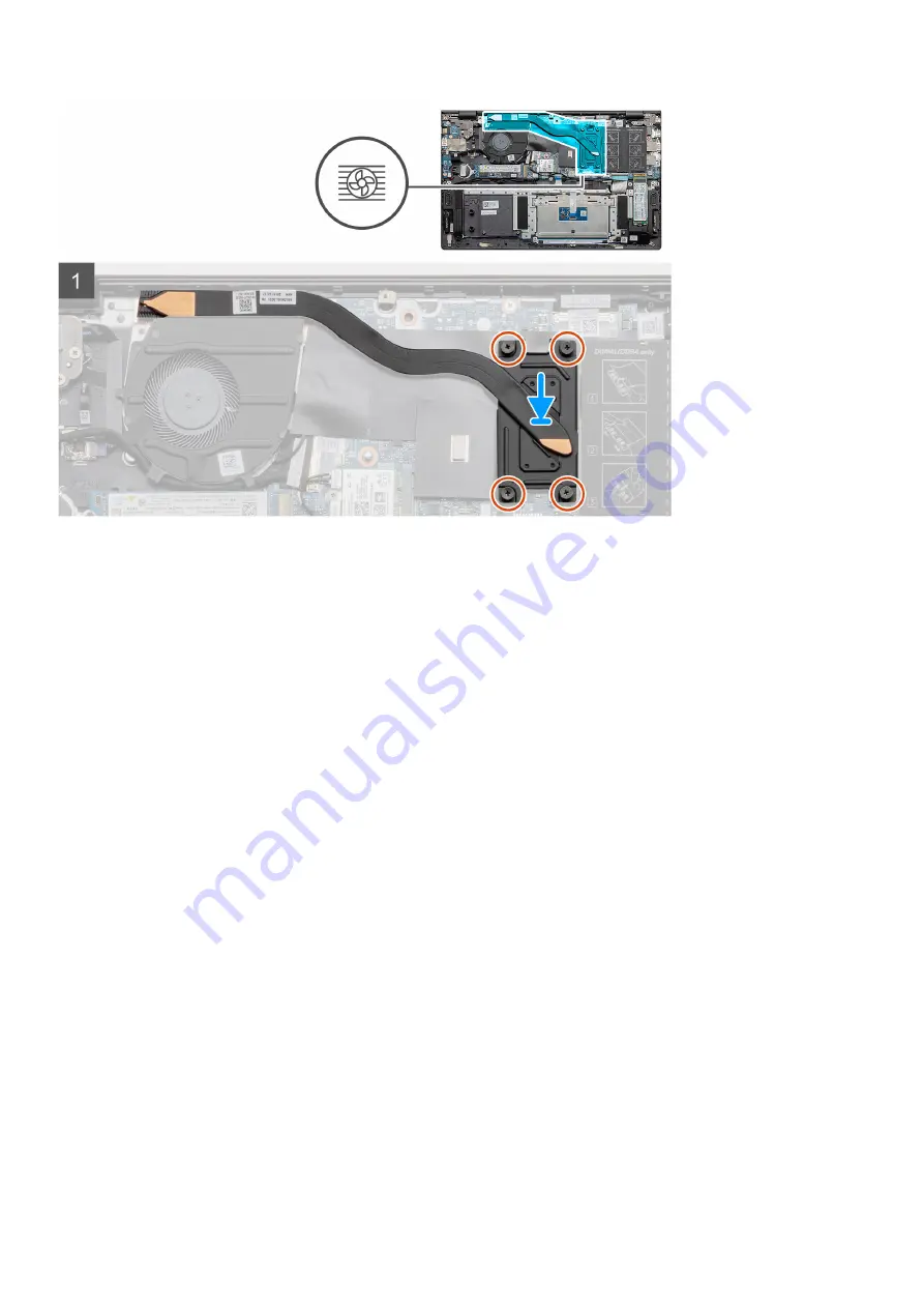
1. Place the heat sink on the system board and align the screw holes on the heat sink with the screw holes on the system

board.

2. In sequential order (as indicated on the heat sink), tighten the four captive screws (M2x3) that secure the heat sink to the

system board.

Next steps

1. Install the 

battery

.

2. Install the 

base cover

.

3. Follow the procedure in 

after working inside your computer

.

System fan

Removing the system fan

Prerequisites

1. Follow the procedure in 

before working inside your computer

.

2. Remove the 

base cover

.

3. Remove the 

battery

.

About this task

The figure indicates the location of the system fan and provides a visual representation of the removal procedure.

Disassembly and reassembly

39

Содержание P102F

Страница 1: ...Vostro 5502 Service Manual Regulatory Model P102F Regulatory Type P102F002 August 2021 Rev A03 ...

Страница 2: ...tial damage to hardware or loss of data and tells you how to avoid the problem WARNING A WARNING indicates a potential for property damage personal injury or death 2020 2021 Dell Inc or its subsidiaries All rights reserved Dell EMC and other trademarks are trademarks of Dell Inc or its subsidiaries Other trademarks may be trademarks of their respective owners ...

Страница 3: ...the memory modules 20 Installing the memory modules 21 Solid state drive 22 Removing the M 2 2280 solid state drive SSD 1 22 Installing the M 2 2280 solid state drive SSD 1 22 Removing the M 2 2230 solid state drive SSD 1 23 Installing the M 2 2230 solid state drive SSD 1 24 Replacing the SSD 1 support bracket 25 Removing the M 2 2280 solid state drive SSD 2 26 Installing the M 2 2280 solid state ...

Страница 4: ...stalling the power button with optional finger reader 52 Touchpad 53 Removing the touchpad 53 Installing the touchpad 54 Display assembly 55 Removing the display assembly 55 Installing the display assembly 58 Palm rest and keyboard assembly 60 Removing the palm rest and keyboard assembly 60 Installing the palm rest and keyboard assembly 61 Chapter 4 Software 63 Downloading Windows drivers 63 Chapt...

Страница 5: ...n Lithium ion batteries 85 Dell SupportAssist Pre boot System Performance Check diagnostics 86 Running the SupportAssist Pre Boot System Performance Check 86 Built in self test BIST 86 System board built in self test M BIST 87 Display panel power rail built in self test L BIST 87 Display panel built in self test LCD BIST 88 Outcome 88 System diagnostic lights 89 Recovering the operating system 90 ...

Страница 6: ...lly touching an unpainted metal surface at the same time as touching a connector on the back of the computer CAUTION Handle components and cards with care Do not touch the components or contacts on a card Hold a card by its edges or by its metal mounting bracket Hold a component such as a processor by its edges not by its pins CAUTION When you disconnect a cable pull on its connector or on its pul...

Страница 7: ...be remotely turned on wake on LAN and suspended into a sleep mode and has other advanced power management features Unplugging pressing and holding the power button for 20 seconds should discharge residual power in the system board Remove the battery from notebooks Bonding Bonding is a method for connecting two or more grounding conductors to the same electrical potential This is done through the u...

Страница 8: ... wire Never use wireless wrist straps Always be aware that the internal wires of a wrist strap are prone to damage from normal wear and tear and must be checked regularly with a wrist strap tester in order to avoid accidental ESD hardware damage It is recommended to test the wrist strap and bonding wire at least once per week ESD Wrist Strap Tester The wires inside of an ESD strap are prone to dam...

Страница 9: ...ts or parts to be returned to Dell it is critical to place these parts in anti static bags for safe transport After working inside your computer About this task After you complete any replacement procedure ensure that you connect any external devices cards and cables before turning on your computer Steps 1 Connect any telephone or network cables to your computer CAUTION To connect a network cable ...

Страница 10: ...emory module 6 Solid state drive shield 7 M 2 2230 SSD 8 Speaker 9 System board 10 Touchpad 11 Palm rest and keyboard assembly 12 Display assembly 13 Power button with fingerprint reader 14 Coin cell battery 15 I O board 16 System fan 17 WLAN card 2 10 Major components of your system ...

Страница 11: ...nts and their part numbers for the original system configuration purchased These parts are available according to warranty coverages purchased by the customer Contact your Dell sales representative for purchase options Major components of your system 11 ...

Страница 12: ... require the following tools Phillips 0 screwdriver Phillips 1 screwdriver Plastic scribe NOTE The 0 screw driver is for screws 0 1 and the 1 screw driver is for screws 2 4 Screw list NOTE When removing screws from a component it is recommended to note the screw type the quantity of screws and then place them in a screw storage box This is to ensure that the correct number of screws and correct sc...

Страница 13: ...id state drive thermal support bracket M1 6x2 2 WLAN M2x3 1 Heat sink NOTE UMA configuration has 4 captive screws NOTE Discrete configuration has 7 captive screws M2x5 35 captive M2x5 35 captive 4 7 System fan M2x2 2 I O board M2x2 4 System board M2x2 2 DC in port M2x3 1 Power button with fingerprint reader M2x3 M1 6x2 1 1 Touchpad M1 6x2 M2x2 3 2 Display assembly M2 5x3 5 6 Disassembly and reasse...

Страница 14: ...r Prerequisites Follow the procedure in before working inside your computer About this task The figure indicates the location of the base cover and provides a visual representation of the removal procedure 14 Disassembly and reassembly ...

Страница 15: ...and work your way around and follow the guidance line indicated in the image to remove the base cover 4 Lift the base cover off the palm rest and keyboard assembly Installing the base cover Prerequisites If you are replacing a component remove the existing component before performing the installation procedure About this task The figure indicates the location of the base cover and provides a visua...

Страница 16: ...16 Disassembly and reassembly ...

Страница 17: ...Lithium ion battery precautions CAUTION Exercise caution when handling Lithium ion batteries Discharge the battery completely before removing it Disconnect the AC power adapter from the system and operate the computer solely on battery power the battery is fully discharged when the computer no longer turns on when the power button is pressed Do not crush drop mutilate or penetrate the battery with...

Страница 18: ...www dell com or authorized Dell partners and resellers Swollen batteries should not be used and should be replaced and disposed properly For guidelines on how to handle and replace swollen Lithium ion batteries see Handling swollen Lithium ion batteries Removing the 3 cell battery UMA discrete Prerequisites NOTE Vostro 5501 also supports 4 cell battery 1 Follow the procedure in before working insi...

Страница 19: ...cell battery and provides a visual representation of the installation procedure Steps 1 Place the battery on the palm rest and keyboard assembly and align the screw holes on the battery with the screw holes on the palmrest and keyboard assembly 2 Install the four screws M2x3 that secure the battery to the system board and palm rest and keyboard assembly 3 Connect the battery cable to the system bo...

Страница 20: ...ure indicates the location of the memory module and provides a visual representation of the removal procedure Steps 1 Lift the mylar covering the memory module 2 Using your finger tips gently pry the retention clips away from the memory module until the memory module pops up 3 Slide and remove the memory module off the memory module slot on the system board 20 Disassembly and reassembly ...

Страница 21: ...a visual representation of the installation procedure Steps 1 Lift the mylar and align the notch on the memory module with the tab on the memory module slot 2 Slide the memory module firmly into the slot at an angle 3 Press the memory module down until it clicks into place NOTE If you do not hear the click remove the memory module and reinstall it Next steps 1 Install the battery 2 Install the bas...

Страница 22: ... state storage About this task The figure indicates the location of the M 2 2280 solid state drive and provides a visual representation of the removal procedure from slot one Steps 1 Remove the single screw M2x3 that secures the solid state drive to the palm rest and keyboard assembly 2 Slide and remove the solid state drive module from the solid state drive slot on the system board Installing the...

Страница 23: ...lid state drive 2 Replace the single M2x3 screw to secure the solid state drive module to the palm rest and keyboard assembly Next steps 1 Install the battery 2 Install the base cover 3 Follow the procedure in after working inside your computer Removing the M 2 2230 solid state drive SSD 1 Prerequisites 1 Follow the procedure in before working inside your computer 2 Remove the base cover 3 Remove ...

Страница 24: ...80 solid state drive in M 2 slot one NOTE M 2 slot two supports one PCIe Gen3 x4 NVMe or SATA solid state drive M 2 2230 or M 2 2280 or one Intel Optane memory H10 with solid state storage NOTE If there is only one solid state drive in the configuration you ordered you can install another solid state drive in the other M 2 slot However you may need a solid state drive bracket sold separately to in...

Страница 25: ...the base cover 3 Follow the procedure in after working inside your computer Replacing the SSD 1 support bracket Prerequisites 1 Follow the procedure in before working inside your computer 2 Remove the base cover 3 Remove the battery 4 Remove the M 2 2280 SSD or M 2 2230 SSD About this task The figure indicates the location of the SSD support bracket and provides a visual representation of the repl...

Страница 26: ...nside your computer 2 Remove the base cover 3 Remove the battery NOTE Depending on the configuration ordered your computer may support a 2230 solid state drive or a 2280 solid state drive in M 2 slot one NOTE M 2 slot two supports one PCIe Gen3 x4 NVMe or SATA solid state drive M 2 2230 or M 2 2280 or one Intel Optane memory H10 with solid state storage About this task The figure indicates the loc...

Страница 27: ...a 2230 solid state drive or a 2280 solid state drive in M 2 slot one NOTE M 2 slot two supports one PCIe Gen3 x4 NVMe or SATA solid state drive M 2 2230 or M 2 2280 or one Intel Optane memory H10 with solid state storage NOTE If there is only one solid state drive in the configuration you ordered you can install another solid state drive in the other M 2 slot However you may need a solid state dri...

Страница 28: ...d state drive SSD 2 Prerequisites 1 Follow the procedure in before working inside your computer 2 Remove the base cover 3 Remove the battery NOTE Depending on the configuration ordered your computer may support a 2230 solid state drive or a 2280 solid state drive in M 2 slot one NOTE M 2 slot two supports one PCIe Gen3 x4 NVMe or SATA solid state drive M 2 2230 or M 2 2280 or one Intel Optane memo...

Страница 29: ...280 solid state drive in M 2 slot one NOTE M 2 slot two supports one PCIe Gen3 x4 NVMe or SATA solid state drive M 2 2230 or M 2 2280 or one Intel Optane memory H10 with solid state storage NOTE If there is only one solid state drive in the configuration you ordered you can install another solid state drive in the other M 2 slot However you may need a solid state drive bracket sold separately to i...

Страница 30: ...Install the battery 2 Install the base cover 3 Follow the procedure in after working inside your computer Removing the thermal support bracket Prerequisites 1 Follow the procedure in before working inside your computer 2 Remove the base cover 3 Remove the battery 4 Remove the SSD 2 About this task The figure provides a visual representation on how to remove a thermal support bracket 30 Disassembly...

Страница 31: ... the thermal support bracket Replacing the thermal support bracket Prerequisites If you are replacing a component remove the existing component before performing the installation procedure About this task The figure provides a visual representation on how to replace thermal support bracket Disassembly and reassembly 31 ...

Страница 32: ...ll battery Removing the coin cell battery Prerequisites 1 Follow the procedure in before working inside your computer 2 Remove the base cover 3 Remove the battery NOTE Removing the coin cell battery resets the BIOS setup program settings to default It is recommended that you note the BIOS setup program settings before removing the coin cell battery About this task The figure indicates the location...

Страница 33: ...the palm rest and keyboard assembly 2 Route the coin cell battery cable as illustrated and connect it to the I O board Next steps 1 Install the battery 2 Install the base cover 3 Follow the procedure in after working inside your computer WLAN card Removing the WLAN card Prerequisites 1 Follow the procedure in before working inside your computer 2 Remove the base cover 3 Remove the battery About th...

Страница 34: ...LAN card 4 Slide and remove the WLAN card from the WLAN card slot Installing the WLAN card Prerequisites If you are replacing a component remove the existing component before performing the installation procedure About this task The figure indicates the location of the WLAN card and provides a visual representation of the installation procedure 34 Disassembly and reassembly ...

Страница 35: ...LAN card bracket on the WLAN card 4 Replace the screw M2x3 to secure the WLAN card bracket to the WLAN card Next steps 1 Install the battery 2 Install the base cover 3 Follow the procedure in after working inside your computer Speakers Removing the speakers Prerequisites 1 Follow the procedure in before working inside your computer 2 Remove the base cover 3 Remove the battery Disassembly and reass...

Страница 36: ...es the speaker cable 4 Unroute the speaker cables from the retention clips on the computer 5 Lift the speakers along with the cable off the palm rest and keyboard assembly Installing the speakers Prerequisites If you are replacing a component remove the existing component before performing the installation procedure About this task The figure indicates the location of the speakers and provides a v...

Страница 37: ...es on the palm rest and keyboard assembly 3 Connect the speaker cable to the system board Next steps 1 Install the battery 2 Install the base cover 3 Follow the procedure in after working inside your computer Heat sink Removing the heat sink UMA Prerequisites NOTE The heat sink type in your computer varies depending on the configuration ordered Disassembly and reassembly 37 ...

Страница 38: ...n the heat sink loosen the four captive screws that secure the heat sink to the system board 2 Lift and remove the heat sink off the palm rest and keyboard assembly Installing the heat sink UMA Prerequisites If you are replacing a component remove the existing component before performing the installation procedure About this task The figure indicates the location of the heat sink and provides a vi...

Страница 39: ...the system board Next steps 1 Install the battery 2 Install the base cover 3 Follow the procedure in after working inside your computer System fan Removing the system fan Prerequisites 1 Follow the procedure in before working inside your computer 2 Remove the base cover 3 Remove the battery About this task The figure indicates the location of the system fan and provides a visual representation of ...

Страница 40: ... the system fan to the palm rest and keyboard assembly 6 Slide and lift the system fan off the palm rest and keyboard assembly Installing the system fan Prerequisites If you are replacing a component remove the existing component before performing the installation procedure About this task The figure indicates the location of the system fan and provides a visual representation of the installation ...

Страница 41: ...the two M2x2 screws to secure the system fan to the palm rest and keyboard assembly 4 Connect the system fan cable to the system board 5 Route the I O cable underneath the system fan and connect on the system board 6 Place the mylar cover back Next steps 1 Install the battery 2 Install the base cover 3 Follow the procedure in after working inside your computer Disassembly and reassembly 41 ...

Страница 42: ...move the coin cell About this task The figure indicates the location of the I O board and provides a visual representation of the removal procedure Steps 1 Locate the I O board on your computer 2 Remove the three M2 5x3 5 screws that secure the left display hinge to the computer and rotate the hinge open to 90 degrees 3 Lift the mylar cover 4 Peel the adhesive tape to unroute the I O cable 42 Disa...

Страница 43: ...ard assembly Installing the I O board Prerequisites If you are replacing a component remove the existing component before performing the installation procedure About this task The figure indicates the location of the I O board and provides a visual representation of the installation procedure Steps 1 Place the I O board on the palm rest and keyboard assembly 2 Align the screw holes on the I O boar...

Страница 44: ...cedure in after working inside your computer System board Removing the system board Prerequisites 1 Follow the procedure in before working inside your computer 2 Remove the base cover 3 Remove the battery 4 Remove the SSD 1 M 2 2280 solid state drive or M 2 2230 solid state drive 5 Remove the SSD 2 M 2 2280 solid state drive or M 2 2230 solid state drive 6 Remove the WLAN card 7 Remove the heat si...

Страница 45: ...Disassembly and reassembly 45 ...

Страница 46: ...nect the touchpad cable from the system board 11 Open the latch and disconnect the keyboard backlight cable from the system board 12 Open the latch and disconnect the keyboard cable from the system board 13 Remove the two screws M2x2 that secure the system board to the palm rest and keyboard assembly 14 Gently release the ports on the system board from the slots on the palm rest and keyboard assem...

Страница 47: ...Disassembly and reassembly 47 ...

Страница 48: ...e system board and lower the latch 6 Adhere the tape that secures the I O cable to the system board 7 Connect the display cable on to the connector on the system board 8 Connect the DC in port cable on to the connector on the system board 9 Place the USB Type C port bracket 10 Replace the two screws M2x3 that secure the USB Type C port bracket to the system board 11 Connect the speaker cable to th...

Страница 49: ...te drive 7 Install the battery 8 Install the base cover 9 Follow the procedure in after working inside your computer DC in port Removing the DC in Prerequisites 1 Follow the procedure in before working inside your computer 2 Remove the base cover 3 Remove the battery About this task The figure indicates the location of the DC in and provides a visual representation of the removal procedure Disasse...

Страница 50: ...keyboard assembly Installing the DC in port Prerequisites If you are replacing a component remove the existing component before performing the installation procedure About this task The figure indicates the location of the DC in port and provides a visual representation of the installation procedure Steps 1 Locate the DC in port on your laptop 2 Replace the single M2x3 screw and connect the DC in ...

Страница 51: ... Remove the I O board About this task The figure indicates the location of the power button with optional fingerprint reader and provides a visual representation of the removal procedure Steps 1 Remove the single screw M2x3 that secures the bracket to the palm rest and keyboard assembly 2 Remove the single screw M1 6x2 that secures the power button with optional fingerprint reader to the palm rest...

Страница 52: ...al fingerprint reader on the palm rest and keyboard assembly 2 Replace the single screw M1 6x2 that secures the power button with optional fingerprint reader to the palm rest and keyboard assembly 3 Plug the fingerprint reader cable into the connector on palm rest and keyboard assembly 4 Adhere the adhesive tape 5 Place the fingerprint reader bracket and replace the single screw M2x3 Next steps 1 ...

Страница 53: ...this task The figure indicates the location of the touchpad and provides a visual representation of the removal procedure Steps 1 Peel adhesive tape and unroute the speaker cable 2 Remove the three M1 6x2 screws that secure the touchpad bracket to the palm rest and keyboard assembly 3 Lift the touchpad bracket off the palm rest and keyboard assembly Disassembly and reassembly 53 ...

Страница 54: ... existing component before performing the installation procedure About this task The figure indicates the location of the component and provides a visual representation of the installation procedure Steps 1 Align and place the touchpad into the slot on the palm rest and keyboard assembly 2 Replace the two M2x2 screws along with the bracket to secure the touchpad to the palm rest and keyboard assem...

Страница 55: ...1 Install the speakers 2 Install the battery 3 Install the base cover 4 Follow the procedure in after working inside your computer Display assembly Removing the display assembly Prerequisites 1 Follow the procedure in before working inside your computer 2 Remove the base cover 3 Remove the battery About this task The figure indicates the location of the display assembly and provides a visual repre...

Страница 56: ...56 Disassembly and reassembly ...

Страница 57: ...Disassembly and reassembly 57 ...

Страница 58: ...crews M2 5x3 5 that secure the right display hinge to the system board 6 Open the display hinges at an angle of 90 degrees 7 Slide the palm rest and keyboard assembly off the display assembly carefully Installing the display assembly Prerequisites If you are replacing a component remove the existing component before performing the installation procedure About this task The figure indicates the loc...

Страница 59: ...Disassembly and reassembly 59 ...

Страница 60: ...ge to the system board 6 Connect the display cable on to the connector on the system board and adhere the tape to the system board Next steps 1 Install the WLAN card 2 Install the battery 3 Install the base cover 4 Follow the procedure in after working inside your computer Palm rest and keyboard assembly Removing the palm rest and keyboard assembly Prerequisites 1 Follow the procedure in before wo...

Страница 61: ...sink About this task The figure indicates the location of the palm rest and keyboard assembly and provides a visual representation of the removal procedure Steps After performing the steps in the pre requisites we are left with the palm rest and keyboard assembly Installing the palm rest and keyboard assembly Prerequisites If you are replacing a component remove the existing component before perfo...

Страница 62: ...y 7 Install the speakers 8 Install the heat sink 9 Install the system fan 10 Install the SSD 1 M 2 2280 solid state drive or M 2 2230 solid state drive 11 Install the SSD 2 M 2 2280 solid state drive or M 2 2230 solid state drive 12 Install the memory module 13 Install the coin cell battery 14 Install the WLAN card 15 Install the battery 16 Install the base cover 17 Follow the procedure in after w...

Страница 63: ...lick Submit NOTE If you do not have the Service Tag use the auto detect feature or manually browse for your notebook model 4 Click Drivers and Downloads 5 Select the operating system installed on your notebook 6 Scroll down the page and select the driver to install 7 Click Download File to download the driver for your notebook 8 After the download is complete navigate to the folder where you saved...

Страница 64: ...m and setup password Boot menu Press F12 when the Dell logo appears to initiate a one time boot menu with a list of the valid boot devices for the system Diagnostics and BIOS Setup options are also included in this menu The devices that are listed on the boot menu depend on the bootable devices in the system This menu is useful when you are attempting to boot to a particular device or to bring up ...

Страница 65: ...one time boot menu by pressing F12 key The one time boot menu displays the devices that you can boot from including the diagnostic option The boot menu options are Removable Drive if available STXXXX Drive NOTE XXXX denotes the SATA drive number Optical Drive if available SATA Hard Drive if available Diagnostics NOTE Choosing Diagnostics displays the SupportAssist diagnostics screen The boot seque...

Страница 66: ...ed Memory Channel Mode Memory Technology DIMM_Slot 1 DIMM_Slot 2 Device Information Panel Type Video Controller Video Memory Wi Fi Device Native Resolution Video BIOS Version Audio Controller Bluetooth Device LOM MAC Address dGPU Video Controller Boot configuration Table 3 Boot configuration Option Description Boot Sequence Allows you to change the order in which the computer attempts to find an o...

Страница 67: ...n is enabled KEK db dbx Integrated Devices Table 4 Integrated device options Option Description Date Time Allows you to set the date and time The change to the system date and time takes effect immediately Camera Allows you to enable or disable camera Enable Camera This option is enabled by default Audio Allows you to turn off all integrated audio By default the Enable Audio option is selected All...

Страница 68: ...e Enable SMART Reporting option is disabled Drive Information Provides information about drive type and device Display Table 6 Display options Option Description Display Brightness Allows you to set the screen brightness when running on battery and AC power The options are Brightness on battery power By default set to 50 Brightness on AC power By default set to 100 EcoPower EcoPower increases the ...

Страница 69: ...tion Battery Configuration Allows the system to run on battery during peak power usage hours The options are Adaptive enabled by default Standard ExpressCharge Primarily AC Use Custom NOTE If Custom Charge is selected you can also configure Custom Charge Start and Custom Charge Stop Advanced Configuration This option enables you to maximize the battery health By default the Enable Advanced Battery...

Страница 70: ...system power option remains blank if it was set to Sleep Lid Switch Allows you to disable the lid switch The options are Enable Lid Switch enabled by default Power On Lid Open enabled by default Intel Speed Shift technology Allows you to enable or disable the Intel Speed Shift Technology support By default Intel Speed Shift technology is enabled Enabling this option allows the operating system to ...

Страница 71: ...on Description Admin Password Allows you to set change or delete the administrator admin password The entries to set password are Enter the old password Enter the new password Press Enter once you enter the new password and again press Enter to confirm the new password NOTE Deleting the admin password deletes the system password if set For this reason you cannot set an admin password if a system p...

Страница 72: ...isabled NOTE If the admin password is set and Enable Admin Setup Lockoutis enabled you cannot view the BIOS setup using F2 or F12 without the admin password If the admin password is set and Enable Admin Setup Lockoutis disabled the BIOS setup can be entered and items that are viewed in Locked mode Master Password Lockout Allows you to disable master password support Enable Master Password Lockout ...

Страница 73: ...etup options control the automatic flow for SupportAssist System Resolution Console and for Dell OS Recovery Tool The options are Off 1 2 Default 3 System management Table 12 System management Option Description Service Tag Displays the service tag of your computer Asset Tag An Asset Tag is a string of 64 characters that are used by IT administrator to uniquely identify a particular system On an a...

Страница 74: ...s feature defines the timeout value for the keyboard backlight when an AC adapter is plugged in the system The options are 5 seconds 10 seconds This option is enabled by default 15 seconds 30 seconds 1 minute 5 minutes 15 minutes Never NOTE If Never is selected the backlight stays on always when the system has AC adapter plugged in Keyboard Backlight Timeout on Battery This feature defines the tim...

Страница 75: ...This option allows you to configure the speed of UEFI boot process Select one of the following options Minimal Thorough enabled by default Auto Extend BIOS POST Time This option allows you to configure the BIOS POST load time Select one of the following options 0 seconds enabled by default 5 seconds 10 seconds Mouse Touchpad This option defines how the system handles mouse and touchpad input Selec...

Страница 76: ...s feature allows the system to dynamically detect high usage of discrete graphics and adjust system parameters for higher performance during that time period Enable Adaptive C states for Discrete Graphics This option is enabled by default Intel Turbo Boost Technology This option allows you to enable or disable the Intel TurboBoost mode of the processor Enable Intel Turbo Boost Technology This opti...

Страница 77: ... Code and click Submit Click Detect Product and follow the instructions on screen 3 If you are unable to detect or find the Service Tag click Choose from all products 4 Choose the Products category from the list NOTE Choose the appropriate category to reach the product page 5 Select your computer model and the Product Support page of your computer appears 6 Click Get drivers and click Drivers and ...

Страница 78: ...to the F12 One Time Boot Menu to see if BIOS UPDATE is listed as a boot option for your system If the option is listed then the BIOS supports this BIOS update option NOTE Only systems with BIOS Flash Update option in the F12 One Time Boot Menu can use this function Updating from the One Time Boot Menu To update your BIOS from the F12 One Time boot menu you need USB drive formatted to the FAT32 fil...

Страница 79: ...The Flash BIOS opens 4 Click Flash from file System setup 79 ...

Страница 80: ...5 Select external USB device 6 Once the file is selected double click the flash target file and click Submit 80 System setup ...

Страница 81: ...7 Click Update BIOS for the system to reboot and flash the BIOS System setup 81 ...

Страница 82: ...8 Click Confirm Update BIOS 82 System setup ...

Страница 83: ...ord Password that you must enter to access and make changes to the BIOS settings of your computer You can create a system password and a setup password to secure your computer CAUTION The password features provide a basic level of security for the data on your computer CAUTION Anyone can access the data that is stored on your computer if it is not locked and left unattended NOTE System and setup p...

Страница 84: ...ing or changing an existing system setup password Prerequisites Ensure that the Password Status is Unlocked in the System Setup before attempting to delete or change the existing System and or Setup password You cannot delete or change an existing System or Setup password if the Password Status is Locked About this task To enter the System Setup press F12 immediately after a power on or reboot Ste...

Страница 85: ...erms of the applicable warranty or service contract including options for replacement by a Dell authorized service technician The guidelines for handling and replacing Lithium ion batteries are as follows Exercise caution when handling Lithium ion batteries Discharge the battery before removing it from the system To discharge the battery unplug the AC adapter from the system and operate the system...

Страница 86: ... computer terminal when the diagnostic tests are performed For more information see https www dell com support kbdoc 000180971 Running the SupportAssist Pre Boot System Performance Check Steps 1 Turn on your computer 2 As the computer boots press the F12 key as the Dell logo appears 3 On the boot menu screen select the Diagnostics option 4 Click the arrow at the bottom left corner Diagnostics fron...

Страница 87: ...f 2 8 blinks Amber x2 then pause then blinks White x8 Repair instruction Indicates a problem with the system board Indicates a problem with the system board System board built in self test M BIST About this task Steps 1 Press and hold both the M key and the power button to initiate M BIST 2 The battery status light illuminates in amber when there is a system board failure 3 Replace the system boar...

Страница 88: ...and then press the power button 2 Release both the D key and the power button when the computer begins POST 3 The display panel begins to display a solid color or cycling through different colors NOTE The sequence of colors may vary depending on the different display panel vendors The user only must ensure that the colors are being displayed correctly without distortion or graphical anomalies 4 Th...

Страница 89: ...indicating no memory or RAM is detected The following table shows different power and battery status light patterns and associated problems Table 21 LED codes Diagnostic light codes Problem description 1 1 TPM Detection Failure 1 2 Unrecoverable SPI Flash Failure 1 3 Short in hinge cable tripped OCP1 1 4 Short in hinge cable tripped OCP2 1 5 EC unable to program i Fuse 1 6 Generic catch all for un...

Страница 90: ...ell SupportAssist OS Recovery see Dell SupportAssist OS Recovery User s Guide at www dell com serviceabilitytools Click SupportAssist and then click SupportAssist OS Recovery Flashing the BIOS About this task It is recommended to flash the BIOS when an update is available or when you replace the system board To flash the BIOS Steps 1 Turn on your computer 2 Go to www dell com support 3 Click Produ...

Страница 91: ...ers provide a modem router combo device Steps 1 Turn off your computer 2 Turn off the modem 3 Turn off the wireless router 4 Wait for 30 seconds 5 Turn on the wireless router 6 Turn on the modem 7 Turn on your computer Drain residual flea power perform hard reset About this task Flea power is the residual static electricity that remains in the computer even after it has been powered off and the ba...

Страница 92: ...able Prerequisites Follow this procedure when disconnecting the ethernet RJ 45 cable from the RJ 45 port to avoid damaging your computer Steps 1 Press down on the securing clip to release it from the port and pull the plug backward 1 2 2 Lift at an angle when disconnecting the ethernet cable from the RJ 45 port Ethernet port 3 4 92 Troubleshooting ...

Страница 93: ...r Express Service Code at www dell com support For more information on how to find the Service Tag for your computer see Locate the Service Tag on your computer Dell knowledge base articles for a variety of computer concerns 1 Go to www dell com support 2 On the menu bar at the top of the Support page select Support Knowledge Base 3 In the Search field on the Knowledge Base page type the keyword t...

Отзывы: