Back to Contents Page
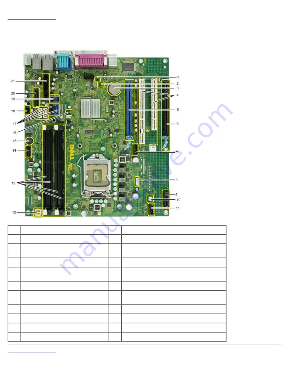
System Board Layout
Dell™ OptiPlex™ 980 Service Manual—Mini-Tower
1
service mode jumper (Service_Mode)
2
RTC reset jumper (RTCRST)
3
battery socket (BATTERY)
4
PCI card connectors ( SLOT 2 & 3)
5
PCI Express x16 card
connector(SLOT1)
6
PCI Express x16 (wired as x4) connector (Slot
4)
7
internal serial card connector (Serial2)
8
speaker connector (INT_SPKR)
9
PCI Express x1 wireless card
connector (PCIE_WLS1)
10
thermal sensor connector THRM3)
11
fan connector (FAN_CPU)
12
power connector (12V POWER)
13
memory module connectors (DIMM_1-
4)
14
front panel connector (FRONTPANEL)
15
internal buzzer (BEEP)
16
password jumper (PSWD)
17
SATA drive connectors (SATA0-3)
18
intruder connector (INTRUDER)
19
internal USB connector (INT_USB)
20
front I/O connector(FIO)
21
power connector (MICRO_PWR)
Back to Contents Page
Содержание OptiPlex 980 - Desktop
Страница 10: ...ft Airborne contaminant level G2 or lower as defined by ISA S71 04 1985 Back to Contents Page ...
Страница 13: ......
Страница 39: ...6 To remove the upper front panel release the tabs 7 Pull out and remove the front panel ...
Страница 45: ...5 Remove the metal cover from the wireless card assembly 6 Disconnect the antennae ...
Страница 47: ...9 Release and remove the antennae 10 Remove the WLAN board from the bracket ...
Страница 50: ...3 Disconnect the fan connector from the system board 4 Remove the screws from the processor fan shroud ...
Страница 55: ...7 Lift the processor cover 8 Remove the processor from the computer ...
Страница 63: ...3 Release the front thermal sensor cable 4 Release the hook to remove the front thermal Sensor ...
Страница 70: ...5 Release the control panel cable 6 Release the hooks and remove the control panel cover ...
Страница 71: ...7 Remove the screws 8 Remove the control panel ...
Страница 81: ...7 Remove the screws from the system board 8 Slide and remove the system board ...


