background image

Steps

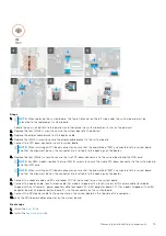
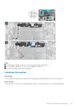
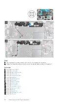
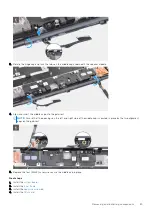
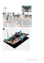
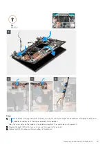
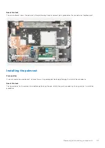
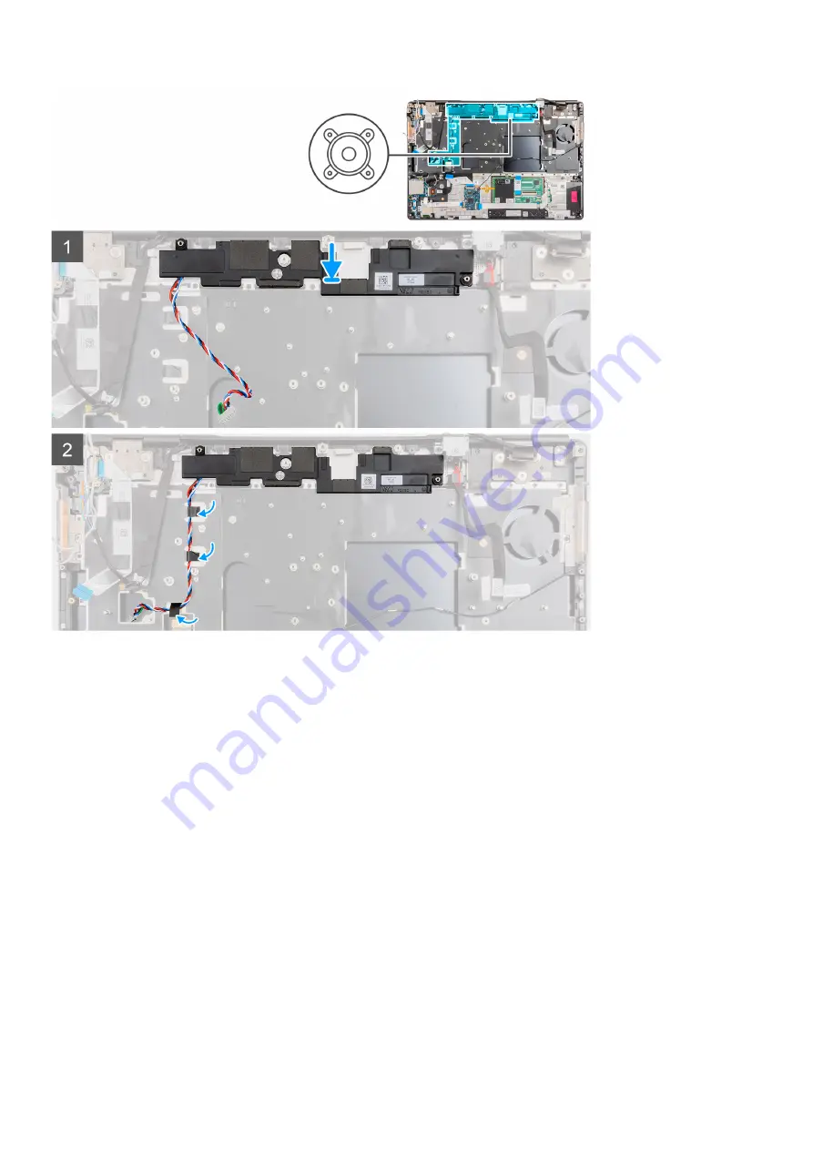
1. Align and place the speaker module into its slot on the top edge of the palmrest.
2. Adhere the three piece adhesive tape to secure the speaker cable in place on the palmrest.

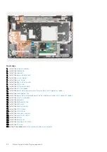
Next steps

1. Install the 

system board

.

2. Install the 

inner frame

.

3. Install the 

heat-sink assembly

.

4. Install the 

GPU card

.

5. Install the 

GPU power cable

.

6. Install the 

keyboard

.

7. Install the 

keyboard lattice

.

8. Install the 

SIM card

.

9. Install the 

primary memory

.

10. Install the 

WWAN card

.

11. Install the 

WLAN card

.

12. Install the 

secondary memory

.

13. Install the 

primary M.2 SSD

.

14. Install the 

battery

.

15. Install the 

base cover

.

16. Install the 

secondary M.2 SSD

.

17. Install the 

SD card

.

82

Removing and installing components

Содержание OptiPlex 7760

Страница 1: ...Precision 7760 Service Manual Regulatory Model P44E Regulatory Type P44E002 July 2021 Rev A01 ...

Страница 2: ...ential damage to hardware or loss of data and tells you how to avoid the problem WARNING A WARNING indicates a potential for property damage personal injury or death 2021 Dell Inc or its subsidiaries All rights reserved Dell EMC and other trademarks are trademarks of Dell Inc or its subsidiaries Other trademarks may be trademarks of their respective owners ...

Страница 3: ...lling the secondary M 2 SSD module 18 Base cover 21 Removing the base cover 21 Installing the base cover 24 Battery 26 Lithium ion battery precautions 26 Removing the battery 27 Installing the battery 28 Solid State Drive 30 Removing the primary M 2 Solid state drive 30 Installing the primary M 2 SSD module 31 Secondary memory module 33 Removing the secondary memory module 33 Installing the second...

Страница 4: ...Power button board with fingerprint reader 61 Removing the power button board assembly with fingerprint reader 61 Installing the power button board assembly with fingerprint reader 62 Power button 63 Removing the power button 63 Installing the power button 64 Power button assembly with fingerprint reader 65 Removing the power button board assembly with fingerprint reader 65 Installing the power bu...

Страница 5: ...or board 109 Removing the P sensor board 109 Installing the P sensor board 110 Display cable 112 Removing the display cable 112 Installing the display cable 113 Display back cover 115 Replacing the display back cover 115 Chapter 3 Drivers and downloads 117 Chapter 4 BIOS setup 118 BIOS overview 118 Entering BIOS setup program 118 Navigation keys 118 Boot Sequence 119 BIOS setup options 119 Updatin...

Страница 6: ...portAssist Pre boot System Performance Check diagnostics 132 Running the SupportAssist Pre Boot System Performance Check 132 System diagnostic lights 133 Recovering the operating system 134 Backup media and recovery options 135 Real Time Clock RTC reset 135 WiFi power cycle 135 Drain residual flea power perform hard reset 136 Chapter 6 Getting help and contacting Dell 137 6 Contents ...

Страница 7: ... not authorized by Dell is not covered by your warranty See the safety instructions that is shipped with the product or at www dell com regulatory_compliance CAUTION Before touching anything inside your computer ground yourself by touching an unpainted metal surface such as the metal at the back of the computer While you work periodically touch an unpainted metal surface to dissipate static electr...

Страница 8: ...the system board Bonding Bonding is a method for connecting two or more grounding conductors to the same electrical potential This is done through the use of a field service electrostatic discharge ESD kit When connecting a bonding wire ensure that it is connected to bare metal and never to a painted or non metal surface The wrist strap should be secure and in full contact with your skin and ensur...

Страница 9: ... a wrist strap tester in order to avoid accidental ESD hardware damage It is recommended to test the wrist strap and bonding wire at least once per week ESD Wrist Strap Tester The wires inside of an ESD strap are prone to damage over time When using an unmonitored kit it is a best practice to regularly test the strap prior to each service call and at a minimum test once per week A wrist strap test...

Страница 10: ... replacement parts or parts to be returned to Dell it is critical to place these parts in anti static bags for safe transport After working inside your computer About this task NOTE Leaving stray or loose screws inside your computer may severely damage your computer Steps 1 Replace all screws and ensure that no stray screws remain inside your computer 2 Connect any external devices peripherals or ...

Страница 11: ...yboard Primary memory module Inner frame Smart card reader Touchpad button SD card reader Heat sink Power button board Power button board with fingerprint reader Power button Power button assembly with fingerprint reader GPU power cable System board Power adapter port GPU card Speaker Middle cap Display assembly Palm rest Display bezel Display panel Display hinges Camera shutter cap Camera P senso...

Страница 12: ...lor may vary with the configuration ordered Table 1 Screw list Component Screw type Quantity Screw image Base cover Captive screws 8 Battery M2x5 3 M 2 2280 PCIe 4 secondary Solid state drive slot 6 M2x3 2 M 2 2230 primary Solid state drive slot 3 slot 4 and or slot 5 M2x3 M2x2 2 1 M 2 2280 primary Solid state drive slot 3 slot 4 and slot 5 M2x3 2 Keyboard M2x2 6 WWAN M2x3 1 WLAN Captive screw 1 M...

Страница 13: ...M2x3 2 Darwin cable bracket M2x3 1 Display cable bracket M2x5 1 System board M2x5 3 GPU card M2x5 4 Middle cap M2x3 3 Hinge screws M2 5x2 5 8 Display panel M2 5x2 5 M2x2 5 2 2 Display hinges M2 5x2 5 8 Major components of Precision 7760 The following image shows the major components of Precision 7760 Removing and installing components 13 ...

Страница 14: ...1 Base cover 2 Battery 3 Middle cap 4 Power adapter port 5 System board 6 Inner frame 7 Palmrest 8 Keyboard 14 Removing and installing components ...

Страница 15: ... representative for purchase options SD card Removing SD card Prerequisites 1 Follow the procedure in before working inside your computer About this task The figure indicates the location of the SD card and provides a visual representation of the removal procedure Steps 1 Press the SD card to release it from the computer 2 Slide the SD card out of the computer Installing SD card Prerequisites If y...

Страница 16: ...t supports only M 2 2280 PCIe Gen4 Solid state drive and does not support any Optane SATA or M 2 2230 Solid state drive 1 Follow the procedure in before working inside your computer 2 Remove the SD card 3 Remove the base cover NOTE Follow this procedure only if the computer is shipped without SSD door configuration About this task The figure indicates the location of the secondary M 2 SSD and prov...

Страница 17: ...For computers without SSD door configuration Removing and installing components 17 ...

Страница 18: ...e M2x3 screw that secures the SSD module into its slot on the computer 4 Slide the SSD release latch to unlock the SSD module 5 Remove the SSD module from the computer 6 Remove the M2x3 screw that secures the SSD thermal plate to the SSD carrier 7 Carefully tilt at an angle and then slide to remove the SSD thermal plate from the SSD module 8 Remove the M 2 2280 SSD from the SSD carrier Installing ...

Страница 19: ... a component remove the existing component before performing the installation procedure About this task The figure indicates the location of the secondary M 2 SSD and provides a visual representation of the installation procedure For computers with SSD door configuration For computers without SSD door configuration Removing and installing components 19 ...

Страница 20: ... thermal plate to the M 2 SSD module 5 Replace the M 2 SSD module in its slot on the computer 6 Replace the M2x3 screw to secure the SSD module in place 7 Slide the SSD release latch to lock the SSD module in place 8 For computers shipped with SSD door configuration a Close the SSD door until it clicks into place Next steps 1 Install the base cover NOTE Follow this procedure only if the computer i...

Страница 21: ...1 Follow the procedure in before working inside your computer 2 Remove the SD card About this task The figure indicates the location of the base cover and provides a visual representation of the removal procedure Removing and installing components 21 ...

Страница 22: ...aptive screws that secure the base cover to the computer 2 For computers shipped without a smart card reader pry open the base cover starting from the recess at the bottom edge of the cover 22 Removing and installing components ...
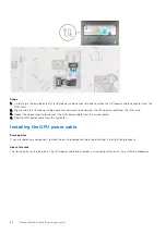
Страница 23: ...may damage the base cover 3 Lift the base cover starting from the bottom edge and push it towards the rear to remove it from the computer NOTE Do not lift the base cover directly upwards to remove as this may damage the rear edge of the cover 4 After removing the base cover if any of the thermal pads for the M 2 SSD WWAN card and or inner frame are detached adhere them to their correct slot on the...

Страница 24: ...r Prerequisites If you are replacing a component remove the existing component before performing the installation procedure About this task The figure indicates the location of the base cover and provides a visual representation of the installation procedure 24 Removing and installing components ...
Страница 25: ...Removing and installing components 25 ...

Страница 26: ... battery precautions CAUTION Exercise caution when handling Lithium ion batteries Discharge the battery as much as possible before removing it from the system This can be done by disconnecting the AC adapter from the system to allow the battery to drain Do not crush drop mutilate or penetrate the battery with foreign objects Do not expose the battery to high temperatures or disassemble battery pac...

Страница 27: ... or crushing a lithium ion battery can be dangerous In such an instance contact Dell technical support for assistance See www dell com contactdell Always purchase genuine batteries from www dell com or authorized Dell partners and resellers Removing the battery Prerequisites 1 Follow the procedure in before working inside your computer 2 Remove the SD card 3 Remove the base cover About this task T...

Страница 28: ...nroute the battery cable from the routing guide in the battery 5 Disconnect the battery cable from the connector on the battery Installing the battery Prerequisites If you are replacing a component remove the existing component before performing the installation procedure About this task The figure indicates the location of the battery and provides a visual representation of the installation proce...

Страница 29: ...Removing and installing components 29 ...

Страница 30: ...stall the SD card 3 Follow the procedure in after working inside your computer Solid State Drive Removing the primary M 2 Solid state drive Prerequisites NOTE For computers shipped with M 2 2280 or 2230 Solid state drive installed in slot 3 slot 4 and or slot 5 NOTE Slot 3 slot 4 and slot 5 supports PCIe Gen3 Optane and SATA Solid state drive 1 Follow the procedure in before working inside your co...

Страница 31: ...to SSD holder d Remove the SSD from the holder 5 Repeat the above steps to remove the other SSD modules in the computer Installing the primary M 2 SSD module Prerequisites NOTE For computers shipped with M 2 2280 or 2230 Solid state drive installed in slot 3 slot 4 and or slot 5 NOTE Slot 3 slot 4 and slot 5 supports PCIe Gen3 Optane and SATA Solid state drive If you are replacing a component remo...

Страница 32: ...he holder c Place the M 2 SSD module onto its slot on the computer d Replace the M2x3 screw to secure the M 2 SSD module to the computer 3 Carefully align and insert the two tabs on the SSD thermal plate into the slots on the inner frame to secure the SSD thermal plate in place 4 Replace the M2x3 screw to secure the SSD thermal plate to the M 2 SSD 5 Repeat the above steps to install the other SSD...

Страница 33: ...ary memory module and provides a visual representation of the removal procedure Steps 1 Pry the securing clips from both side of the memory module until the memory module pops up 2 Remove the memory module from the memory module slot Installing the secondary memory module Prerequisites If you are replacing a component remove the existing component before performing the installation procedure About...

Страница 34: ... reinstall it Next steps 1 Install the base cover 2 Install the SD card 3 Follow the procedure in after working inside your computer SIM card Removing the SIM card Prerequisites 1 Follow the procedure in before working inside your computer 2 Remove the SD card 3 Remove the base cover About this task The figure indicates the location of the SIM card and provides a visual representation of the remov...

Страница 35: ...ing 2 Flip the right edge of the SIM card cover to open it 3 Remove the SIM card from the SIM card slot Installing the SIM card Prerequisites If you are replacing a component remove the existing component before performing the installation procedure About this task The figure indicates the location of the SIM card and provides a visual representation of the installation procedure Removing and inst...

Страница 36: ...nstall the SD card 3 Follow the procedure in after working inside your computer WLAN card Removing the WLAN card Prerequisites 1 Follow the procedure in before working inside your computer 2 Remove the SD card 3 Remove the base cover About this task The figure indicates the location of the WLAN card and provides a visual representation of the removal procedure 36 Removing and installing components...

Страница 37: ...lide at an angle and remove the WLAN card from the connector on the system board Installing the WLAN card Prerequisites If you are replacing a component remove the existing component before performing the installation procedure About this task The figure indicates the location of the WLAN card and provides a visual representation of the installation procedure Removing and installing components 37 ...

Страница 38: ...y black triangle Black 2 Align the notch on the WLAN card with the WLAN connector and insert the WLAN card at an angle into the WLAN card slot 3 Align and place the WLAN card bracket to secure the WLAN antenna cables to the WLAN card 4 Tighten the captive screw to secure the WLAN card bracket to the system board Next steps 1 Install the base cover 2 Install the SD card 3 Follow the procedure in af...

Страница 39: ...WWAN card 3 Disconnect the antenna cables from the connector on the WWAN card 4 Slide and remove the WWAN card from its slot on the system board NOTE When replacing the system board the sticker indicating the WWAN antenna cable connections must be relocated to the replacement system board Installing the WWAN card Prerequisites If you are replacing a component remove the existing component before p...

Страница 40: ... 2 Align and slide the WWAN card to its slot on the system board 3 Place the WWAN card bracket above the WWAN card to secure the antenna cables 4 Tighten the M2x3 screw to secure the WWAN card bracket to the system board Next steps 1 Install the base cover 2 Install the SD card 3 Follow the procedure in after working inside your computer Keyboard lattice Removing the keyboard lattice Prerequisites...

Страница 41: ...nts and working your way around the sides and bottom edge 2 Remove the keyboard lattice from the keyboard Installing the keyboard lattice Prerequisites If you are replacing a component remove the existing component before performing the installation procedure About this task The figure indicates the location of the keyboard lattice and provides a visual representation of the installation procedure...

Страница 42: ...cedure in after working inside your computer Keyboard Removing the keyboard Prerequisites 1 Follow the procedure in before working inside your computer 2 Remove the SD card 3 Remove the base cover 4 Remove the battery 5 Remove the keyoard lattice About this task The figure indicates the location of the keyboard and provides a visual representation of the removal procedure 42 Removing and installin...

Страница 43: ...he left and the right sides of the keyboard 5 Carefully unroute the keyboard backlight FPC and the keyboard FPC through the opening on the palmrest 6 Remove the keyboard from the computer Installing the keyboard Prerequisites If you are replacing a component remove the existing component before performing the installation procedure About this task The figure indicates the location of the keyboard ...

Страница 44: ... palmrest 5 Turn over the system at 90 angle to access the keyboard FPC and the keyboard backlight FPC 6 Connect the keyboard backlight FPC and the keyboard FPC to the connectors on the system board NOTE Ensure that you fold the keyboard data cable in perfect alignment Next steps 1 Install the keyboard lattice 2 Install the battery 3 Install the base cover 4 Install the SD card 5 Follow the proced...

Страница 45: ...emove the keyoard lattice 6 Remove the keyboard About this task The figure indicates the location of the primary memory module and provides a visual representation of the removal procedure Steps 1 Remove the M2x3 screw that secures the memory shield in place 2 Slide the memory shield towards the right side of the computer and lift the shield from the memory module Removing and installing component...

Страница 46: ...acing a component remove the existing component before performing the installation procedure About this task The figure indicates the location of the primary memory module and provides a visual representation of the installation procedure Steps 1 Align the notch on the memory module with the tab on the memory module slot 2 Slide the memory module firmly into the slot at an angle and press the memo...

Страница 47: ...ard lattice 3 Install the battery 4 Install the base cover 5 Install the SD card 6 Follow the procedure in after working inside your computer Inner frame Removing the inner frame Prerequisites 1 Follow the procedure in before working inside your computer 2 Remove the SD card 3 Remove the base cover 4 Remove the battery 5 Remove the WLAN card 6 Remove the WWAN card 7 Remove the primary M 2 SSD Abou...

Страница 48: ...nnect the keyboard FPC and the keyboard backlight FPC from the connector on the touchpad module 4 Remove the ten M2x3 screws that secure the inner frame to the computer chassis 5 Remove the inner frame from the computer while carefully unthreading the keyboard FPC and keyboard backlight FPC through the opening on the inner frame NOTE If the thermal pad attached to the bottom side of the inner fram...

Страница 49: ...g a component remove the existing component before performing the installation procedure About this task The figure indicates the location of the inner frame and provides a visual representation of the installation procedure Removing and installing components 49 ...

Страница 50: ...with WWAN card a Connect the two Darwin antenna cables to the connector on the system board b Align and place the Darwin bracket to secure the Darwin antenna cables to the system board c Replace the M2x3 screw to secure the Darwin bracket in place Next steps 1 Install the WWAN card 2 Install the WLAN card 3 Install the primary M 2 SSD 4 Install the battery 5 Install the base cover 6 Install the SD...

Страница 51: ...ct the touchpad buttons FPC from the touchpad 2 Disconnect the smart card reader FFC from the connector on the USH daughter board 3 Peel the smart card reader FFC from the touchpad 4 Remove the two M2x2 5 screws that secure the smart card reader to the computer 5 Remove the smart card reader from the computer Installing the smart card reader Prerequisites If you are replacing a component remove th...

Страница 52: ...1 Install the inner frame 2 Install the WWAN card 3 Install the WLAN card 4 Install the primary M 2 SSD 5 Install the battery 6 Install the base cover 7 Install the SD card 8 Follow the procedure in after working inside your computer Touchpad button Removing the Touchpad buttons Prerequisites 1 Follow the procedure in before working inside your computer 2 Remove the SD card 3 Remove the base cover...

Страница 53: ...he touchpad buttons FPC from the connector on the touchpad 3 Remove the two M2x2 5 screws that secure the touchpad buttons to the palmrest 4 Remove the touchpad buttons from the palmrest Installing the Touchpad buttons Prerequisites If you are replacing a component remove the existing component before performing the installation procedure About this task The figure indicates the location of the to...

Страница 54: ...e inner frame 2 Install the WWAN card 3 Install the WLAN card 4 Install the primary M 2 SSD 5 Install the battery 6 Install the base cover 7 Install the SD card 8 Follow the procedure in after working inside your computer SD card reader Removing SD card reader Prerequisites 1 Follow the procedure in before working inside your computer 2 Remove the SD card 3 Remove the base cover 4 Remove the batte...

Страница 55: ...the bottom side of the computer 3 Remove the M2 5x2 5 screw that secures the SD card reader in place 4 Slide and remove the SD card reader with its FPC out of the computer Installing SD card reader Prerequisites If you are replacing a component remove the existing component before performing the installation procedure About this task The figure indicates the location of the SD card reader and prov...

Страница 56: ... reader FPC to the connector on the system board Next steps 1 Install the inner frame 2 Install the keyboard 3 Install the keyboard lattice 4 Install the WWAN card 5 Install the WLAN card 6 Install the primary M 2 SSD 7 Install the battery 8 Install the base cover 9 Install the SD card 10 Follow the procedure in after working inside your computer Heat sink Removing the heat sink assembly Prerequis...

Страница 57: ...card a Loosen the eight captive screws that secure the heat sink assembly to the system board NOTE Loosen the captive screws in the order stamped onto the heat sink assembly next to the screws 8 7 6 5 4 3 2 1 5 Carefully lift the heat sink assembly to remove it from the computer NOTE While lifting the heat sink assembly the thermal pads attached to the bottom side of the heat sink can stick to the...

Страница 58: ...y Installing the heat sink assembly Prerequisites If you are replacing a component remove the existing component before performing the installation procedure About this task The figure indicates the location of the keyboard and provides a visual representation of the installation procedure 58 Removing and installing components ...
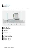
Страница 59: ... 2 3 4 5 6 7 8 4 Connect the two fan cables to the connector on the system board 5 Adhere the power adapter cable on the heat sink assembly 6 Connect the power adapter cable to the connector on the system board Next steps 1 Install the battery 2 Install the base cover 3 Install the SD card 4 Follow the procedure in after working inside your computer Power button board Removing the power button boa...

Страница 60: ...th the power button board FFC from the computer 5 Disconnect the power button board FFC from the power button board Installing the power button board Prerequisites If you are replacing a component remove the existing component before performing the installation procedure About this task The figure indicates the location of the power button board and provides a visual representation of the installa...

Страница 61: ...Install the battery 3 Install the base cover 4 Install the SD card 5 Follow the procedure in after working inside your computer Power button board with fingerprint reader Removing the power button board assembly with fingerprint reader Prerequisites 1 Follow the procedure in before working inside your computer 2 Remove the SD card 3 Remove the base cover 4 Remove the battery 5 Remove the heat sink...

Страница 62: ...rd FFC from the palmrest 6 Remove the two M2x3 screws that secure the power button board to the computer 7 Remove the power button board with the power button board FFC from the computer 8 Disconnect the power button board FFC from the power button board Installing the power button board assembly with fingerprint reader Prerequisites If you are replacing a component remove the existing component b...

Страница 63: ...board 7 Replace the power button board assembly with fingerprint reader FPC bracket above the power button daughter board 8 Replace the M2x3 screw to secure the power button board assembly with fingerprint reader FPC bracket in place Next steps 1 Install the heat sink assembly 2 Install the battery 3 Install the base cover 4 Install the SD card 5 Follow the procedure in after working inside your c...

Страница 64: ...the power button in its slot on the computer 2 Remove the power button from the computer Installing the power button Prerequisites If you are replacing a component remove the existing component before performing the installation procedure About this task The figure indicates the location of the power button and provides a visual representation of the installation procedure 64 Removing and installi...

Страница 65: ...inside your computer Power button assembly with fingerprint reader Removing the power button board assembly with fingerprint reader Prerequisites 1 Follow the procedure in before working inside your computer 2 Remove the SD card 3 Remove the base cover 4 Remove the battery 5 Remove the heat sink assembly About this task The figure indicates the location of the power button board assembly with fing...

Страница 66: ...board FFC from the palmrest 6 Remove the two M2x3 screws that secure the power button board to the computer 7 Remove the power button board with the power button board FFC from the computer 8 Disconnect the power button board FFC from the power button board Installing the power button assembly with fingerprint reader Prerequisites If you are replacing a component remove the existing component befo...

Страница 67: ...ery 4 Install the base cover 5 Install the SD card 6 Follow the procedure in after working inside your computer GPU power cable Removing the GPU power cable Prerequisites 1 Follow the procedure in before working inside your computer 2 Remove the SD card 3 Remove the base cover 4 Remove the battery 5 Remove the keyboard lattice 6 Remove the keyboard About this task The figure indicates the location...

Страница 68: ...at the above steps to disconnect the GPU power cable from the system board 4 Peel the GPU power cable from the computer Installing the GPU power cable Prerequisites If you are replacing a component remove the existing component before performing the installation procedure About this task The figure indicates the location of the GPU power cable and provides a visual representation of the installati...

Страница 69: ...ard lattice 3 Install the battery 4 Install the base cover 5 Install the SD card 6 Follow the procedure in after working inside your computer System board Removing the system board Prerequisites 1 Follow the procedure in before working inside your computer 2 Remove the SD card 3 Remove the secondary M 2 SSD 4 Remove the base cover 5 Remove the battery 6 Remove the SIM card 7 Remove the secondary m...

Страница 70: ...rd connector 3 Darwin antenna cable connector 4 Secondary M 2 SSD connector 5 Fan cable connector 6 FPC beam connector 7 Display cable connector 8 IR camera Touchscreen cable connector 9 Power adapter port connector 10 Fan cable connector 11 Battery cable connector 12 Touchpad cable cpnnector 13 Secondary memory module slot 14 USH daughter board cable connector 15 WLAN card connector 16 SIM card s...

Страница 71: ...ory module slot 2 GPU power cable connector 3 SD card reader cable 4 Speaker cable connector 5 Coin cell battery cable connector NOTE For models shipped with a discrete GPU card Removing and installing components 71 ...

Страница 72: ...chpad FFC USH daughter board FFC for models shipped with a USH daughter board and power button board FFC from the system board 5 Remove the four M2x3 screws that secure the two FPC beam connectors to the system board and the GPU card NOTE For computers shipped with a UMA GPU card remove the two M2x3 screws that secure the single FPC beam connector to the system board and the GPU card 6 Remove the ...

Страница 73: ...ed from the system board anytime after the system board is removed from the computer re adhere the bracket onto the system board 12 Remove the system board from the computer Installing the system board Prerequisites If you are replacing a component remove the existing component before performing the installation procedure About this task The figure indicates the location of the system board and pr...

Страница 74: ...74 Removing and installing components ...
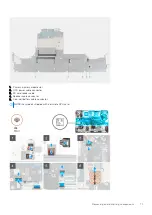
Страница 75: ...board and the GPU card NOTE For UMA models replace the two M2x3 screws to secure the single FPC beam connector to the system board and the GPU card NOTE When installing an FPC beam connector ensure that the end marked MB is connected to the system board and that the alignment pins on the connector are inserted into the openings on the boards 7 Connect the speaker cable and SD card reader FPC to th...

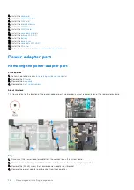
Страница 76: ...r port Prerequisites 1 Follow the procedure in before working inside your computer 2 Remove the SD card 3 Remove the base cover 4 Remove the heat sink assembly About this task The figure indicates the location of the power adapter port and provides a visual representation of the removal procedure Steps 1 Disconnect the power adapter cable from the connector on the system board 2 Peel and unroute t...

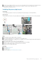
Страница 77: ...ion procedure Steps 1 Align and place the power adapter cable on the computer 2 Place the power adapter port into its compartment on the computer chassis 3 Firmly place the cable clam into its compartment on the computer chassis and route the power adapter cable through the cut out on the system board 4 Place the power adapter port bracket on the power adapter port 5 Replace the M2x3 screw to secu...

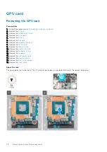
Страница 78: ... the secondary memory 8 Remove the WLAN card 9 Remove the WWAN card 10 Remove the primary M 2 SSD 11 Remove the keyboard lattice 12 Remove the keyboard 13 Remove the GPU power cable 14 Remove the primary memory 15 Remove the heat sink assembly 16 Remove the inner frame About this task The figure indicates the location of the GPU card and provides a visual representation of the removal procedure 78...

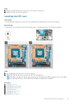
Страница 79: ... procedure Steps 1 Align and place the GPU card into its slot on the palmrest 2 Replace the three M2x5 screws to secure the GPU card to the palmrest NOTE When installing an FPC beam connector ensure that the end marked MB is connected to the system board and that the alignment pins on the connector are inserted into the openings on the boards Next steps 1 Install the inner frame 2 Install the heat...

Страница 80: ...SD card 3 Remove the secondary M 2 SSD 4 Remove the base cover 5 Remove the battery 6 Remove the SIM card 7 Remove the secondary memory 8 Remove the WLAN card 9 Remove the WWAN card 10 Remove the primary M 2 SSD 11 Remove the keyboard lattice 12 Remove the keyboard 13 Remove the GPU power cable 14 Remove the GPU card 15 Remove the primary memory 16 Remove the heat sink assembly 17 Remove the inner...

Страница 81: ...3 Remove the speaker module from the computer Installing the speaker Prerequisites If you are replacing a component remove the existing component before performing the installation procedure About this task The figure indicates the location of the speaker and provides a visual representation of the installation procedure Removing and installing components 81 ...

Страница 82: ...3 Install the heat sink assembly 4 Install the GPU card 5 Install the GPU power cable 6 Install the keyboard 7 Install the keyboard lattice 8 Install the SIM card 9 Install the primary memory 10 Install the WWAN card 11 Install the WLAN card 12 Install the secondary memory 13 Install the primary M 2 SSD 14 Install the battery 15 Install the base cover 16 Install the secondary M 2 SSD 17 Install th...

Страница 83: ...ve the WLAN card 9 Remove the WWAN card 10 Remove the primary M 2 SSD 11 Remove the keyboard lattice 12 Remove the keyboard 13 Remove the GPU power cable 14 Remove the GPU card 15 Remove the primary memory 16 Remove the heat sink assembly 17 Remove the inner frame 18 Remove the system board About this task The figure indicates the location of the speaker and provides a visual representation of the...

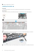
Страница 84: ...location of the middle cap and provides a visual representation of the installation procedure Steps 1 With the open side of the middle hinge cap facing down push the cap into the right display hinge cap at an angle while tucking the WWAN antennas into its hollow center 2 Push the other side of the cap into the left display hinge cap and tuck the display cable into the middle cap hollow center 84 R...

Страница 85: ...ure that the openings on the left and right side of the middle cap is secured in place by the two alignment pegs on the palmrest 5 Replace the four M2x3 screws to secure the middle cap in place Next steps 1 Install the system board 2 Install the inner frame 3 Install the heat sink assembly 4 Install the GPU card Removing and installing components 85 ...

Страница 86: ...sembly Prerequisites 1 Follow the procedure in before working inside your computer 2 Remove the SD card 3 Remove the secondary M 2 SSD 4 Remove the base cover 5 Remove the battery 6 Remove the SIM card 7 Remove the secondary memory 8 Remove the WLAN card 9 Remove the WWAN card 10 Remove the primary M 2 SSD 11 Remove the keyboard lattice 12 Remove the keyboard 13 Remove the primary memory 14 Remove...

Страница 87: ...Removing and installing components 87 ...

Страница 88: ...les and the Darwin cables from the palmrest 3 Remove the eight M2 5x2 5 screws that secure the hinges to the palmrest 4 Remove the display assembly from the palmrest Installing the display assembly Prerequisites If you are replacing a component remove the existing component before performing the installation procedure About this task The figure indicates the location of the display assembly and pr...

Страница 89: ...e display assembly to fit the display assembly to the palmrest Align the screw holes on the hinges on the display assembly to the screw holes on the palmrest 2 Replace the eight M2 5x2 5 screws to secure the hinges to the palmrest 3 Adhere the WWAN cables and Darwin cables to the palmrest Removing and installing components 89 ...

Страница 90: ...s 1 Follow the procedure in before working inside your computer 2 Remove the SD card 3 Remove the secondary M 2 SSD 4 Remove the base cover 5 Remove the battery 6 Remove the SIM card 7 Remove the secondary memory 8 Remove the WLAN card 9 Remove the WWAN card 10 Remove the primary M 2 SSD 11 Remove the keyboard lattice 12 Remove the keyboard 13 Remove the power button board or power button board as...

Страница 91: ... Installing the palmrest Prerequisites If you are replacing a component remove the existing component before performing the installation procedure About this task The figure indicates the palmrest and before performing the pre installation parts procedures for any palmrest installation procedure Removing and installing components 91 ...

Страница 92: ...stall the touchpad button 13 Install the power button board or power button board assembly with fingerprint reader 14 Install the smart card reader 15 Install the keyboard 16 Install the keyboard lattice 17 Install the SIM card 18 Install the primary memory 19 Install the WWAN card 20 Install the WLAN card 21 Install the secondary memory 22 Install the primary M 2 SSD 23 Install the battery 24 Ins...

Страница 93: ...e WWAN card 10 Remove the primary M 2 SSD 11 Remove the keyboard lattice 12 Remove the keyboard 13 Remove the GPU power cable 14 Remove the GPU card 15 Remove the primary memory 16 Remove the heat sink assembly 17 Remove the inner frame 18 Remove the system board 19 Remove the speakers 20 Remove the middlecap 21 Remove the display assembly About this task The figure indicates the location of the d...

Страница 94: ...e outside edge of the display bezel using your hands using a screw driver or other sharp objects may damage the display cover 3 Remove the display bezel from the display assembly Installing the display bezel non touch Prerequisites If you are replacing a component remove the existing component before performing the installation procedure About this task The figure indicates the display bezel and p...

Страница 95: ... 5 Install the inner frame 6 Install the heat sink assembly 7 Install the GPU card 8 Install the GPU power cable 9 Install the keyboard 10 Install the keyboard lattice 11 Install the SIM card 12 Install the primary memory 13 Install the WWAN card 14 Install the WLAN card 15 Install the secondary memory 16 Install the primary M 2 SSD 17 Install the battery 18 Install the base cover 19 Install the s...

Страница 96: ...rd 9 Remove the WWAN card 10 Remove the primary M 2 SSD 11 Remove the keyboard lattice 12 Remove the keyboard 13 Remove the SD card reader 14 Remove the GPU power cable 15 Remove the GPU card 16 Remove the primary memory 17 Remove the heat sink assembly 18 Remove the inner frame 19 Remove the system board 20 Remove the speakers 21 Remove the middlecap 22 Remove the display assembly 23 Remove the d...

Страница 97: ...Removing and installing components 97 ...

Страница 98: ...98 Removing and installing components ...
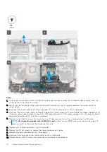
Страница 99: ... connector and then disconnect the display cable from the back of the display panel 7 Remove the display panel form the display assembly 8 Remove the display panel NOTE The support brackets attached to the display panel are defined as a single service assembly part and cannot be further disassembled Installing the display panel non touch Prerequisites If you are replacing a component remove the ex...

Страница 100: ...100 Removing and installing components ...
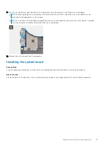
Страница 101: ...ign the display panel with the tabs on the display assembly 5 Replace the two M2 5X2 5 and two M2x2 5 screws to secure the display panel to the display assembly Next steps 1 Install the display bezel 2 Install the display assembly 3 Install the middlecap 4 Install the speakers 5 Install the system board 6 Install the inner frame 7 Install the heat sink assembly 8 Install the GPU card 9 Install the...

Страница 102: ...SSD 4 Remove the base cover 5 Remove the battery 6 Remove the SIM card 7 Remove the secondary memory 8 Remove the WLAN card 9 Remove the WWAN card 10 Remove the primary M 2 SSD 11 Remove the keyboard lattice 12 Remove the keyboard 13 Remove the SD card reader 14 Remove the GPU power cable 15 Remove the GPU card 16 Remove the primary memory 17 Remove the heat sink assembly 18 Remove the inner frame...

Страница 103: ...s Installing the display hinge non touch Prerequisites If you are replacing a component remove the existing component before performing the installation procedure About this task The figure indicates the display hinge and provides a visual representation of the installation procedure Removing and installing components 103 ...

Страница 104: ...nstall the secondary memory 19 Install the primary M 2 SSD 20 Install the battery 21 Install the base cover 22 Install the secondary M 2 SSD 23 Install the SD card 24 Follow the procedure in after working inside your computer Camera shutter cap Removing camera shutter cap Prerequisites 1 Follow the procedure in before working inside your computer 2 Remove the SD card 3 Remove the secondary M 2 SSD...

Страница 105: ...mera shutter cap from the camera module Installing camera shutter cap Prerequisites If you are replacing a component remove the existing component before performing the installation procedure About this task The figure indicates the location of the camera shutter cap and provides a visual representation of the installation procedure Steps 1 Align the cap with the display back cover so that the red...

Страница 106: ...cover 21 Install the secondary M 2 SSD 22 Install the SD card 23 Follow the procedure in after working inside your computer Camera Removing the camera non touch Prerequisites 1 Follow the procedure in before working inside your computer 2 Remove the SD card 3 Remove the secondary M 2 SSD 4 Remove the base cover 5 Remove the battery 6 Remove the SIM card 7 Remove the secondary memory 8 Remove the W...

Страница 107: ... camera module 3 Gently pry the camera shutter cap from the top edge of the camera shutter and remove it from the display back cover 4 Gently pry the camera module from the display back cover Installing the camera Prerequisites If you are replacing a component remove the existing component before performing the installation procedure About this task The figure indicates the camera and provides a v...

Страница 108: ...6 Install the system board 7 Install the inner frame 8 Install the heat sink assembly 9 Install the GPU card 10 Install the GPU power cable 11 Install the SD card reader 12 Install the keyboard 13 Install the keyboard lattice 14 Install the SIM card 15 Install the primary memory 16 Install the WWAN card 17 Install the WLAN card 18 Install the secondary memory 19 Install the primary M 2 SSD 20 Inst...

Страница 109: ...ove the keyboard lattice 12 Remove the keyboard 13 Remove the SD card reader 14 Remove the GPU power cable 15 Remove the GPU card 16 Remove the primary memory 17 Remove the heat sink assembly 18 Remove the inner frame 19 Remove the system board 20 Remove the speakers 21 Remove the middlecap 22 Remove the display assembly 23 Remove the display bezel 24 Remove the display panel About this task The f...

Страница 110: ...ensor board 4 Remove the P sensor board Installing the P sensor board Prerequisites If you are replacing a component remove the existing component before performing the installation procedure About this task The figure indicates the P sensor board and provides a visual representation of the installation procedure 110 Removing and installing components ...
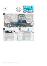
Страница 111: ...nstall the heat sink assembly 9 Install the GPU card 10 Install the GPU power cable 11 Install the SD card reader 12 Install the keyboard 13 Install the keyboard lattice 14 Install the SIM card 15 Install the primary memory 16 Install the WWAN card 17 Install the WLAN card 18 Install the secondary memory 19 Install the primary M 2 SSD 20 Install the battery 21 Install the base cover 22 Install the...

Страница 112: ...oard lattice 12 Remove the keyboard 13 Remove the SD card reader 14 Remove the GPU power cable 15 Remove the GPU card 16 Remove the primary memory 17 Remove the heat sink assembly 18 Remove the inner frame 19 Remove the system board 20 Remove the speakers 21 Remove the middlecap 22 Remove the display assembly 23 Remove the display bezel 24 Remove the display panel 25 Remove the P sensor About this...

Страница 113: ... the routing channels 4 Remove the display cable from the display back cover Installing the display cable Prerequisites If you are replacing a component remove the existing component before performing the installation procedure About this task The figure indicates the display cable and provides a visual representation of the installation procedure Removing and installing components 113 ...

Страница 114: ...he display bezel 4 Install the display assembly 5 Install the middlecap 6 Install the speakers 7 Install the system board 8 Install the inner frame 9 Install the heat sink assembly 10 Install the GPU card 11 Install the GPU power cable 12 Install the SD card reader 13 Install the keyboard 14 Install the keyboard lattice 15 Install the SIM card 16 Install the primary memory 17 Install the WWAN card...

Страница 115: ...AN card 10 Remove the primary M 2 SSD 11 Remove the keyboard lattice 12 Remove the keyboard 13 Remove the SD card reader 14 Remove the GPU power cable 15 Remove the GPU card 16 Remove the primary memory 17 Remove the heat sink assembly 18 Remove the inner frame 19 Remove the system board 20 Remove the speakers 21 Remove the middlecap 22 Remove the display assembly 23 Remove the display bezel 24 Re...

Страница 116: ...he inner frame 13 Install the heat sink assembly 14 Install the GPU card 15 Install the GPU power cable 16 Install the SD card reader 17 Install the keyboard 18 Install the keyboard lattice 19 Install the SIM card 20 Install the primary memory 21 Install the WWAN card 22 Install the WLAN card 23 Install the secondary memory 24 Install the primary M 2 SSD 25 Install the battery 26 Install the base ...

Страница 117: ...Drivers and downloads When troubleshooting downloading or installing drivers it is recommended that you read the Dell knowledge base article Drivers and Downloads FAQs 3 Drivers and downloads 117 ...

Страница 118: ...lled and enabling or disabling base devices Topics BIOS overview Entering BIOS setup program Navigation keys Boot Sequence BIOS setup options Updating the BIOS in Windows Updating the BIOS in Linux and Ubuntu One time boot menu Updating the BIOS from the F12 One Time boot menu System and setup password Clearing BIOS System Setup and System passwords BIOS overview The BIOS manages data flow between...

Страница 119: ...ng F12 key The one time boot menu displays the devices that you can boot from including the diagnostic option The boot menu options are Removable Drive if available STXXXX Drive if available NOTE XXX denotes the SATA drive number Optical Drive if available SATA Hard Drive if available Diagnostics The boot sequence screen also displays the option to access the System Setup screen BIOS setup options...

Страница 120: ...ount Displays the number of cores on the processor Processor ID Displays the processor identification code Current Clock Speed Displays the current processor clock speed Minimum Clock Speed Displays the minimum processor clock speed Maximum Clock Speed Displays the maximum processor clock speed Processor L2 Cache Displays the Processor L2 cache size unit is KB Processor L3 Cache Displays the Proce...

Страница 121: ...rmation of the computer WiGig Device Displays the WiGig device information of the computer Bluetooth Device Displays the bluetooth device information of the computer Passthrough MAC Address Displays the unique MAC address information of the computer Battery Information Displays the battery health charging state and AC adapter information Boot Sequence Boot Sequence Displays the boot sequence Boot ...

Страница 122: ...nu Video LCD Brightness Set the panel brightness independently for Battery and AC power Switchable Graphics Allows to switch between the Integrated graphics and the discrete graphics controller Primary Video Slot Allows to set the primary video slot Table 8 System setup options Security menu Security Admin Password Set change or delete the administrator password System Password Set change or delet...

Страница 123: ...ons Secure Boot menu Secure Boot Secure Boot Enable Enable or disable the secure boot feature Secure Boot Mode Modifies the behavior of Secure Boot to allow evaluation or enforcement of UEFI driver signatures Expert Key Management Expert Key Management Enable or disable Expert Key Management Custom Mode Key Management Select the custom values for expert key management Table 10 System setup options...

Страница 124: ...Lock function when computer boots Fn Lock Options Enable or disable the Fn lock mode Fastboot Enable to set the speed of the boot process Default Thorough Extend BIOS POST Time Configure additional pre boot delay Full Screen Logo Enable or disable to display full screen logo Warnings and Errors Sets the boot process to pause when Warnings or Errors are detected MAC Address Pass Through Sets the MA...

Страница 125: ...olution menu SupportAssist System Resolution Auto OS Recovery Threshold Control the automatic boot flow for SupportAssist System Resolution Console and for Dell OS Recovery tool SupportAssist OS Recovery Enable or disable the boot flow for SupportAssist OS Recovery tool in the even of certain system errors BIOSConnect Enable or disable BIOSConnect Updating the BIOS in Windows Prerequisites It is r...

Страница 126: ...covery key is not known this can result in data loss or an unnecessary operating system re install For more information on this subject see Knowledge Article https www dell com support article sln153694 Updating your system BIOS using a USB flash drive About this task If the computer cannot load into Windows but there is still a need to update the BIOS download the BIOS file using another computer...

Страница 127: ...ic option The boot menu options are Removable Drive if available STXXXX Drive if available NOTE XXX denotes the SATA drive number Optical Drive if available SATA Hard Drive if available Diagnostics The boot sequence screen also displays the option to access the System Setup screen Updating the BIOS from the F12 One Time boot menu Update your computer BIOS using the BIOS update exe file that is cop...

Страница 128: ... USB port of the computer 2 Turn on the computer and press F12 to access the One Time Boot Menu select BIOS Update using the mouse or arrow keys then press Enter The flash BIOS menu is displayed 3 Click Flash from file 4 Select external USB device 5 Select the file and double click the flash target file and then click Submit 6 Click Update BIOS The computer restarts to flash the BIOS 7 The compute...

Страница 129: ...assword if the Password Status is Locked About this task To enter the System Setup press F12 immediately after a power on or reboot Steps 1 In the System BIOS or System Setup screen select System Security and press Enter The System Security screen is displayed 2 In the System Security screen verify that Password Status is Unlocked 3 Select System Password update or delete the existing system passw...

Страница 130: ...wer off state either connected to AC power or with battery only 1 Press and hold both the M key on the keyboard and the power button to initiate M BIST 2 With both the M key and the power button held down the battery indicator LED may exhibit two states a OFF No fault detected with the system board b AMBER Indicates a problem with the system board 3 If there is a failure with the system board the ...

Страница 131: ...o power supplied to the LCD 3 For cases when a 2 7 error code is shown check to see if the display cable is properly connected 4 For cases when a 2 8 error code is shown replace the system board LCD Built in Self Test BIST Dell laptops have a built in diagnostic tool that helps you determine if the screen abnormality you are experiencing is an inherent problem with the LCD screen of the Dell lapto...

Страница 132: ...nostics performs a complete check of your hardware The Dell SupportAssist Pre boot System Performance Check diagnostics is embedded with the BIOS and is launched by the BIOS internally The embedded system diagnostics provides a set of options for particular devices or device groups allowing you to Run tests automatically or in an interactive mode Repeat tests Display or save test results Run thoro...

Страница 133: ...stics tool If problem persists replace the system board 2 2 System board failure included BIOS corruption or ROM error Flash latest BIOS version If problem persists replace the system board 2 3 No memory RAM detected Confirm that the memory module is installed properly If problem persists replace the memory module 2 4 Memory RAM failure Reset and swap memory modules among the slots If problem pers...

Страница 134: ...1 Memory DIMM power rail failure Reset and swap memory modules among the slots If problem persists replace the memory module 4 2 CPU Power Cable connection issue Run the PSU BIST If problem persists replace the system board power supply or cabling NOTE Blinking 3 3 3 LEDs on Lock LED Caps Lock or Nums Lock Power button LED without Fingerprint reader and Diagnostic LED indicates failure to provide ...

Страница 135: ...nected from the system during the process or the power button is held longer than 40 seconds the RTC reset process gets aborted The RTC reset will reset the BIOS to defaults un provision Intel vPro and reset the system date and time The following items are unaffected by the RTC reset Service Tag Asset Tag Ownership Tag Admin Password System Password HDD Password Key Databases System Logs TPM on an...

Страница 136: ... power also known as a performing a hard reset is also a common troubleshooting step if your computer does not power on or boot into the operating system To drain residual flea power perform a hard reset Steps 1 Turn off your computer 2 Disconnect the power adapter from your computer 3 Remove the base cover 4 Remove the battery 5 Press and hold the power button for 20 seconds to drain the flea pow...

Страница 137: ...r Express Service Code at www dell com support For more information on how to find the Service Tag for your computer see Locate the Service Tag on your computer Dell knowledge base articles for a variety of computer concerns 1 Go to www dell com support 2 On the menu bar at the top of the Support page select Support Knowledge Base 3 In the Search field on the Knowledge Base page type the keyword t...

Отзывы: