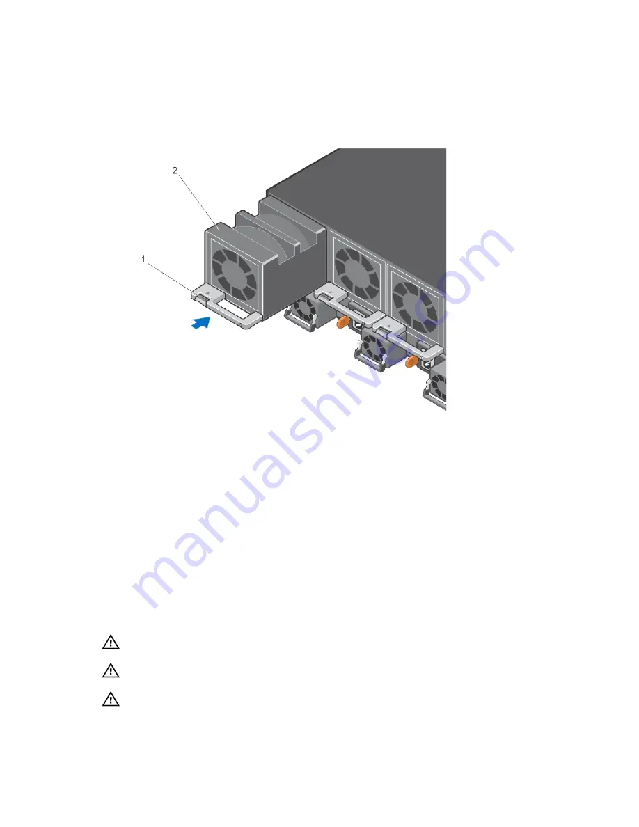
The fan modules are field replaceable. Module slot 0 is on the left side of the chassis; module slot 4 is on
the right side of the chassis.
1.
Take the fan module out of the shipping box.
2.
Use the grab handle to slide the fan module into the switch fan slot, as shown below.
Figure 7. Installing a Fan Module
1.
Release latch
2. Fan module 0/Slot 0
Installing AC Power Supplies
The chassis requires four power supplies to be installed for normal configuration. The airflow direction
must be from I/O to Utility.
Important Points to Remember for Installing an AC Power Supply
• The power supply unit (PSU) slides into the slot smoothly. Do not force a PSU into a slot as this action
may damage the PSU or the chassis.
• The chassis supports AC power supplies with air-flow direction from I/O to Utility.
• For PSUs, a LED indicates the power status.
• To view the log messages, use the
show logging
command. For more information, refer to the
System Logs chapters of the
Dell Networking OS Command Line Reference Guide for the Z9500
Switch
and
Dell Networking OS Configuration Guide for the Z9500 Switch
.
WARNING: Although the switch can run on two PSUs, Dell Networking requires using four PSUs
for full redundancy and proper cooling.
WARNING: The Utility panel consists of four slots numbered from 0 to 3. Insert PSUs in slots 0, 1,
2, and 3.
WARNING: The PSU edge connector is at the bottom. Avoid installing the PSU upside down.
Z9500 Installation
29
Содержание Networking Z9500
Страница 1: ...Dell Networking Installation Guide for the Z9500 Switch ...
Страница 6: ...6 ...
Страница 8: ...8 ...
Страница 16: ...16 ...
Страница 26: ...1 Additional screw to restrict front back movement of the switch 2 Main screw 26 Z9500 Installation ...
Страница 38: ...38 ...
Страница 40: ...40 ...


