background image

Wireless Local Area Network (WLAN) Card : Dell Latitude E4300 Service Manual

file:///C|/Biz%20Client/2015/Lola%20(Defect%20Fix)/wlan.htm[5/25/2015 11:14:06 AM]

Back to Contents Page

 Wireless Local Area Network (WLAN) Card

Dell™ Latitude™ E4300 Service Manual


Removing a WLAN Card


Replacing a WLAN Card

CAUTION: 

Before working inside the computer, read the safety information that shipped with the

computer. For additional safety best practices information, see the Regulatory Compliance Homepage on

www.dell.com at: www.dell.com/regulatory_compliance.

Your computer supports a Wireless Local Area Network (WLAN) card. If you ordered a WLAN card with your computer, the

card is already installed.

Removing a WLAN Card

1.  Follow the instructions in 

What You Need to Know For Your Safety

2.  Close the display and turn the computer upside-down. 

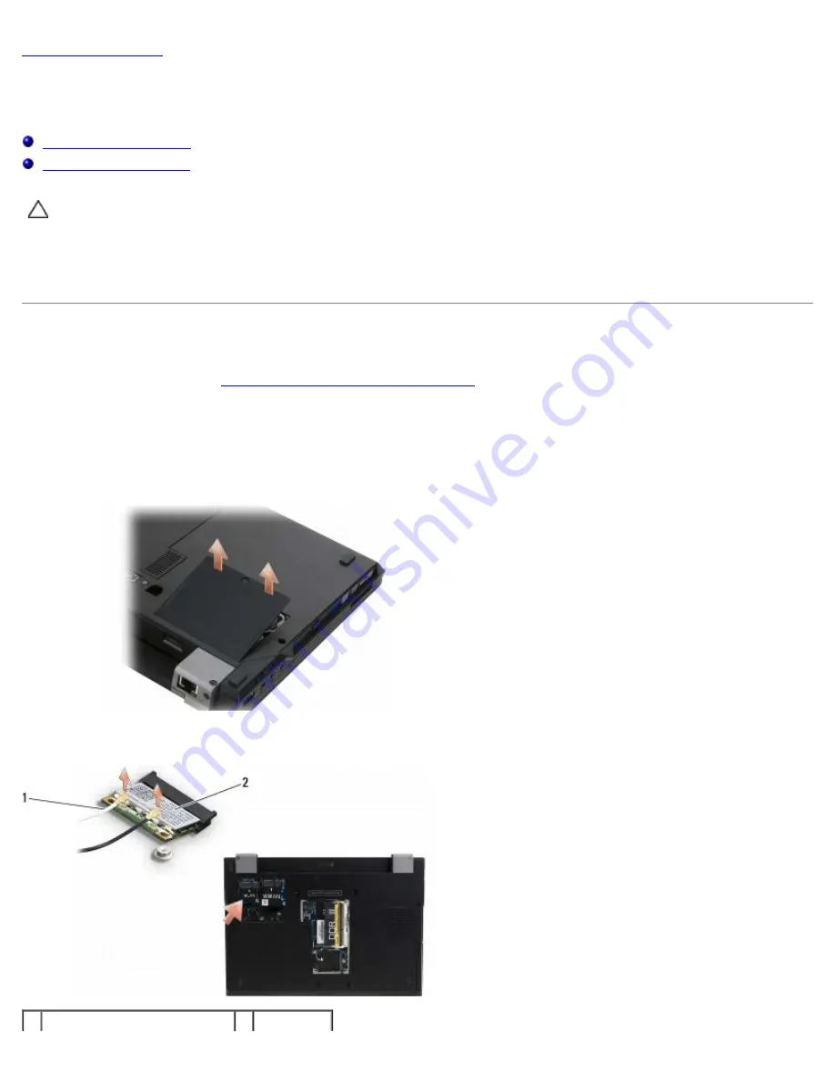
3.  Loosen the captive screw on the WLAN/WWAN cover. 

4.  Remove the WLAN/WWAN cover. 

5.  Disconnect the antenna cables from the WLAN card. 

1 antenna cable connectors (2) 2 WLAN card

Содержание Latitude E4300

Страница 1: ...ot applicable This product incorporates copyright protection technology that is protected by method claims of certain U S patents and other intellectual property rights owned by Macrovision Corporation and other rights owners Use of this copyright protection technology must be authorized by Macrovision Corporation and is intended for home and other limited viewing uses only unless otherwise author...

Страница 2: ...the computer is either turned off or is not receiving power Reseat the power cable into both the power connector on the back of the computer and the electrical outlet If the computer is plugged into a power strip ensure that the power strip is plugged into an electrical outlet and that the power strip is turned on Bypass power protection devices power strips and power extension cables to verify th...

Страница 3: ...ther On Off or Flashing Light Pattern Problem Description Suggested Resolution No memory modules are detected If two or more memory modules are installed remove the modules see Removing a Memory Module then reinstall one module see Replacing a Memory Module and restart the computer If the computer starts normally continue to install additional memory modules one at a time until you have identified...

Страница 4: ...address read value expecting value See Lockups and Software Problems Memory odd even logic failure at address read value expecting value See Lockups and Software Problems Memory write read failure at address read value expecting value See Lockups and Software Problems Memory size in cmos invalid See Lockups and Software Problems No boot device available strike F1 to retry boot F2 for setup utility...

Страница 5: ...ell xxx W AC adapter or greater for best system performance strike the F3 key before the F1 or F2 key if you do not want to see power warning messages again strike the F1 key to continue F2 to run the setup utility Connect the correct AC adapter to the computer or docking station The computer is docked and only battery power is detected This can happen if the power adapter is missing the power cor...

Страница 6: ...to immediately back up your data and replace your hard drive by calling your support desk or dell Contact Dell for assistance see Contacting Dell Your power adapter does not supply enough power to run the attached docking station either undock or insert an appropriate adapter strike the F1 key to shutdown Connect the correct AC adapter Your system is docked but the AC adapter type cannot be determ...

Страница 7: ...ies media is optional and may not ship with your computer NOTE The Dell Diagnostics only operate on Dell computers Starting the Dell Diagnostics From Your Hard Drive Before running the Dell Diagnostics enter the system setup program to review your computer s configuration information and ensure that the device you want to test is displayed in the system setup program and is active For information ...

Страница 8: ... the test window to return to the Dell Diagnostics Main Menu 7 Close the Main Menu window to exit the Dell Diagnostics and restart the computer Starting the Dell Diagnostics From the Drivers and Utilities Media Before running the Dell Diagnostics enter the system setup program to review your computer s configuration information and ensure that the device you want to test is displayed in the system...

Страница 9: ...m the optical drive Dell Diagnostics Main Menu After the Dell Diagnostics loads the following menu appears Option Function Test Memory Run the stand alone memory test Test System Run system diagnostics Exit Exit the diagnostics Press Tab to select the test you want to run and then press Enter NOTE It is recommended that you select Test System to run a complete test on your computer Selecting Test ...

Страница 10: ...formation in the device list in the left pane of the screen NOTE The device list may not display the names of all components installed on your computer or all devices attached to your computer Parameters Allows you to customize the test if applicable by changing the test settings Solving Problems Follow these tips when troubleshooting your computer If you added or removed a part before the problem...

Страница 11: ... bootable floppy disk and restart the computer Clean the drive or disk Check the cable connections Run the Hardware Troubleshooter See Hardware Troubleshooter Run the Dell Diagnostics See Dell Diagnostics Optical drive problems NOTE High speed optical drive vibration is normal and may cause noise which does not indicate a defect in the drive or the media NOTE Because of different regions worldwide...

Страница 12: ...page on www dell com at www dell com regulatory_compliance Check the Microsoft Outlook Express security settings If you cannot open your e mail attachments 1 In Outlook Express click Tools Options Security 2 Click Do not allow attachments to remove the checkmark as needed Ensure that you are connected to the Internet Ensure that you have subscribed to an Internet provider With the Outlook Express ...

Страница 13: ...u want to use first Operating system not found Contact Dell see Contacting Dell IEEE 1394 Device Problems CAUTION Before working inside your computer read the safety information that shipped with your computer For additional safety best practices information see the Regulatory Compliance Homepage on www dell com at www dell com regulatory_compliance NOTE Your computer supports only IEEE 1394a stan...

Страница 14: ...your mouse press and hold the power button for at least 8 to 10 seconds until the computer turns off and then restart your computer A program stops responding End the program 1 Press Ctrl Shift Esc simultaneously to access the Task Manager 2 Click the Applications tab 3 Click to select the program that is no longer responding 4 Click End Task A program crashes repeatedly NOTE Most software include...

Страница 15: ...se a virus scanning program to check the hard drive floppy disks CDs or DVDs Save and close any open files or programs and shut down your computer through the Start menu Memory Problems CAUTION Before working inside your computer read the safety information that shipped with your computer For additional safety best practices information see the Regulatory Compliance Homepage on www dell com at www...

Страница 16: ... power button to resume normal operation If the power light is off The computer is either turned off or is not receiving power Reseat the power cable in the power connector on the back of the computer and the electrical outlet Bypass power strips power extension cables and other power protection devices to verify that the computer turns on properly Ensure that any power strips being used are plugg...

Страница 17: ...d Other Hardware View installed printers or fax printers 2 If the printer is listed right click the printer icon 3 Click Properties Ports For a parallel printer ensure that the Print to the following port s setting is LPT1 Printer Port For a USB printer ensure that the Print to the following port s setting is USB Reinstall the printer driver See the printer documentation for information on reinsta...

Страница 18: ...tup diagram supplied with the speakers If your speakers have volume controls adjust the volume bass or treble to eliminate distortion Adjust the Windows volume control Click or double click the speaker icon in the lower right corner of your screen Ensure that the volume is turned up and that the sound is not muted Disconnect headphones from the headphone connector Sound from the speakers is automa...

Страница 19: ...use controller which affects pointer movement and the operation of the touch pad or mouse buttons run the Mouse test in the Pointing Devices test group in the Dell Diagnostics see Dell Diagnostics Reinstall the touch pad driver See Reinstalling Drivers and Utilities in the Setup and Quick Reference Guide Video and Monitor Problems CAUTION Before working inside your computer read the safety informa...

Страница 20: ...active e mail notification of software and hardware updates for your computer The service is free and can be customized for content format and how frequently you receive notifications To enroll for the Dell Technical Update service go to support dell com technicalupdate Dell Support Utility The Dell Support Utility is installed on your computer and available from the Dell Support icon on the taskb...

Страница 21: ...the help file for the Dell Support Utility View frequently asked questions Learn more about the Dell Support Utility Turn the Dell Support Utility off Double Clicking the Dell Support Icon Double click the icon to manually check your computing environment view frequently asked questions access the help file for the Dell Support Utility and view Dell Support settings For more information about the ...

Страница 22: ...de the computer read the safety information that shipped with the computer For additional safety best practices information see the Regulatory Compliance Homepage on www dell com at www dell com regulatory_compliance CAUTION Many repairs may only be done by a certified service technician You should only perform troubleshooting and simple repairs as authorized in your product documentation or as di...

Страница 23: ...evices from their electrical outlets NOTICE To disconnect a network cable first unplug the cable from your computer and then unplug it from the network wall jack 4 Disconnect any telephone or network cables from the computer 5 Remove any installed cards from the smart card slot and the 8 in 1 memory card reader NOTICE To help prevent damage to the system board you must remove the battery from the ...

Страница 24: ...damage to the computer use only the battery designed for this particular Dell computer Do not use batteries designed for other Dell computers 1 Connect any external devices such as a port replicator battery slice or cool slice and replace any cards such as a smart card 2 Connect any telephone or network cables to your computer 3 Replace the battery Slide the battery into the battery bay until it c...

Страница 25: ...age Battery Slice Dell Latitude E4300 Service Manual Top View Bottom View Detaching the Battery Slice Attaching the Battery Slice The battery slice attaches to the bottom of the laptop and can be charged while attached to the laptop or separately Top View 1 docking connector 2 AC adapter connector 3 power status light 4 release lever Bottom View ...

Страница 26: ...nel Mobile PC Power Options Change what closing the lid does b Under the When I close the lid drop down menu select Do nothing c Pull the laptop release lever to release the laptop from the battery slice 1 battery slice 2 release lever 4 Lift the back edge of the laptop up and slide the laptop toward the back of the battery slice Attaching the Battery Slice NOTE After attaching the battery slice t...

Страница 27: ...Lola 20 Defect 20Fix bslice htm 5 25 2015 11 14 04 AM 1 laptop 2 docking connector 3 battery slice 4 battery slice hooks 2 2 Press the laptop onto the battery slice until you feel a click to indicate that the laptop is firmly seated 3 Turn on the laptop Back to Contents Page ...

Страница 28: ...metal housing of the hard drive if you remove the hard drive from the computer while the drive is hot NOTICE To prevent data loss turn off your computer before removing the hard drive Do not remove the hard drive while the computer is on in sleep mode NOTICE Hard drives are extremely fragile even a slight bump can damage the drive 1 Follow the instructions in What You Need to Know For Your Safety ...

Страница 29: ... hard drive NOTICE Use firm and even pressure to slide the hard drive into place Excessive force may result in damage to the connector NOTE This procedure assumes that you have completed the removal procedure first 1 Secure the bezel to the hard drive with the M3 x 3 mm screw 2 Slide the hard drive into the hard drive connector until the drive is fully seated 3 Replace the two M3 x 3 mm screws sec...

Страница 30: ...or additional safety best practices information see the Regulatory Compliance Homepage on www dell com at www dell com regulatory_compliance Your computer supports a Wireless Local Area Network WLAN card If you ordered a WLAN card with your computer the card is already installed Removing a WLAN Card 1 Follow the instructions in What You Need to Know For Your Safety 2 Close the display and turn the...

Страница 31: ...l procedure first 1 Slide the WLAN card into the connector at a 30 degree angle to the system board 2 Press the card down onto the alignment post and hold it in position 3 Replace the M2 x 3 mm screw to secure the WLAN card 4 Reconnect the appropriate antenna cables to the WLAN card If the WLAN card has two triangles on the label white and black connect the white antenna cable to the connector lab...

Страница 32: ...Wireless Local Area Network WLAN Card Dell Latitude E4300 Service Manual file C Biz 20Client 2015 Lola 20 Defect 20Fix wlan htm 5 25 2015 11 14 06 AM ...

Страница 33: ... with the computer For additional safety best practices information see the Regulatory Compliance Homepage on www dell com at www dell com regulatory_compliance Your computer supports a Wireless Wide Area Network WWAN card If you ordered a WWAN card with your computer the card is already installed Removing a WWAN Card 1 Follow the instructions in What You Need to Know For Your Safety 2 Close the d...

Страница 34: ...board and realign the card NOTICE To avoid damage to the WWAN card ensure the cables are not under the card when you click the card into place NOTICE Install the WWAN card into the compartment shown in the above photograph Do not install it in any other location 1 Slide the WWAN card into the connector at a 30 degree angle 2 Press the card down onto the alignment post and hold in position 3 Replac...

Страница 35: ...alled you must remove DIMM B first Your computer supports the following memory configurations Size Socket Windows XP Windows Vista 512 MB DIMM A X X 1 GB DIMM A X X 2 GB DIMM A or DIMM A and DIMM B X X 3 GB DIMM A and DIMM B X X 4 GB DIMM A or DIMM A and DIMM B X 8 GB DIMM A and DIMM B X Removing a Memory Module CAUTION Before working inside the computer read the safety information that shipped wi...

Страница 36: ... retaining clips on each end of the memory module connector until the module pops up 1 memory module retaining clips 2 2 memory module 3 DIMM B module 4 DIMM A module 6 Remove the module by grasping it at the side edges and pulling it away from the connector Place the module into anti static packaging such as an anti static bag Replacing a Memory Module CAUTION Before working inside the computer r...

Страница 37: ...alled properly the computer may not boot properly No error message indicates this failure 6 Replace the memory cover and tighten the captive screws NOTICE If the cover is difficult to close remove the memory module and reinstall it Forcing the cover to close may damage your computer 7 Follow the instructions in After Working on Your Computer Verifying Memory Capacity 1 Set the computer upright and...

Страница 38: ...Memory Dell Latitude E4300 Service Manual file C Biz 20Client 2015 Lola 20 Defect 20Fix memory htm 5 25 2015 11 14 07 AM Back to Contents Page ...

Страница 39: ...afety best practices information see the Regulatory Compliance Homepage on www dell com at www dell com regulatory_compliance If you ordered a Latitude On card with your computer the card is already installed It is located in the memory bay Removing the Latitude On Card 1 Follow the instructions in What You Need to Know For Your Safety 2 Close the display and turn the computer upside down 3 Loosen...

Страница 40: ... On Card NOTICE Install the Latitude On card into the compartment shown in the above photograph Do not install it in any other location 1 Reseat the Latitude On card in the memory bay 2 Reconnect the black and gray Latitude On cables to their respective connectors as indicated on the card 3 Replace the M2 x 3 mm screw to secure the Latitude On card to the computer base 4 Replace the memory cover 5...

Страница 41: ...Latitude On Card Dell Latitude E4300 Service Manual file C Biz 20Client 2015 Lola 20 Defect 20Fix lat on htm 5 25 2015 11 14 08 AM ...

Страница 42: ...ur Safety 2 Open the display as far as it will go 3 Insert a plastic scribe into the notch on the right side of the LED dashboard cover beside the power button and carefully pry it up to loosen the LED dashboard cover 1 scribe tool 2 notch 4 Remove the LED dashboard cover Replacing the LED Dashboard Cover CAUTION Before working inside the computer read the safety information that shipped with the ...

Страница 43: ...board Cover Dell Latitude E4300 Service Manual file C Biz 20Client 2015 Lola 20 Defect 20Fix ledboard htm 5 25 2015 11 14 08 AM 3 Follow the instructions in After Working on Your Computer Back to Contents Page ...

Страница 44: ...o replace Be careful when removing and handling the keyboard 1 Follow the instructions in What You Need to Know For Your Safety 2 Remove the LED dashboard cover see Removing the LED Dashboard Cover 3 Remove the three M2 x 3 mm screws at the top of the keyboard NOTE Lift the keyboard carefully to ensure that you do not pull on the display cable 4 Lift the keyboard only enough to hold it up and then...

Страница 45: ...he keyboard hook the tabs along the front edge of the keyboard into the palm rest first and then secure the keyboard in place NOTE This procedure assumes that you have completed the removal procedure first 1 Insert the keyboard connector into the connector slot being careful to insert the five tabs underneath the palm rest cover 2 Replace the three M2 x 3 mm screws at the top of the keyboard 1 M2 ...

Страница 46: ...nstructions in What You Need to Know For Your Safety 2 Close the display and turn the computer upside down 3 Remove the four M2 5 x 4 mm screws securing the display assembly to the back of the computer 4 Turn the computer rightside up and open the display 180 degrees 5 Remove the LED dashboard cover see Removing the LED Dashboard Cover 6 Gently lift the display to unseat its hinges taking care not...

Страница 47: ... computer base Replacing the Display Assembly NOTE This procedure assumes that you have completed the removal procedure first 1 Thread the two longer antenna cables through the hole in the system board located just below the radio switch board 2 Turn the computer over and thread the cables through the cable guides in the WLAN WWAN compartment 3 Replace the WLAN WWAN cover and then turn the compute...

Страница 48: ...moval of the bezel from the display back cover requires extreme care to avoid damaging the bezel 3 Starting at the middle bottom of the display panel use your fingers to lift the inner edge of the bezel place your fingers under the inner edge of the bezel and roll the outer edge of the bezel free of the display back cover 4 Starting at the edges of the bottom of the display panel use your fingers ...

Страница 49: ...four M2 5 x 5 mm screws two per side that secure the display hinges to the display back cover 1 hinges 2 2 M2 5 x 5 mm screws 4 5 Free the hinges from the display cable left side and display antenna cables right side Removing the Display Panel 1 Follow the instructions in What You Need to Know For Your Safety 2 Remove the display assembly see Removing the Display Assembly 3 Remove the display beze...

Страница 50: ... 20Fix display htm 5 25 2015 11 14 10 AM 1 display panel brackets 2 2 M2 x 3 mm screws 4 3 display panel 5 Gently remove each bracket by pulling it away from the display 1 display panel 2 display panel brackets 2 6 Lift the display panel away from the display back cover and rotate it forward ...

Страница 51: ...n each side of the panel and then secure it by replacing the two M2 x 3 mm screws 4 Replace the display bezel see Replacing the Display Bezel 5 Replace the display assembly see Replacing the Display Assembly 6 Follow the instructions in After Working on Your Computer Replacing the Display Hinges NOTE This procedure assumes that you have completed the removal procedure first 1 Re thread the display...

Страница 52: ...e LCD cable board to the display back cover 6 Lift the LCD cable board from the display back cover 1 LCD cable board 2 display back cover Replacing the LCD Cable NOTE This procedure assumes that you have completed the removal procedure first 1 Reseat the LCD cable board in the display back cover 2 Replace the M2 x 5 mm screw securing the LCD cable board to the display base 3 Replace the display pa...

Страница 53: ... touching an unpainted metal surface such as the back panel on the computer If you ordered a camera with your computer the camera is already installed Removing the Camera 1 Follow the instructions in What You Need to Know For Your Safety 2 Remove the LED dashboard cover see Removing the LED Dashboard Cover 3 Remove the keyboard see Removing the Keyboard 4 Remove the display assembly see Removing t...

Страница 54: ...camera board to the alignment posts on the display cover 2 Re thread the display cables through the hinges 3 Replace the display hinges see Removing the Display Hinges 4 Replace the display panel see Replacing the Display Panel 5 Replace the display bezel see Replacing the Display Bezel 6 Replace the display assembly see Replacing the Display Assembly 7 Follow the instructions in After Working on ...

Страница 55: ...es information see the Regulatory Compliance Homepage on www dell com at www dell com regulatory_compliance 1 Follow the instructions in What You Need to Know For Your Safety 2 Remove the LED dashboard cover see Removing the LED Dashboard Cover 3 Remove the keyboard see Removing the Keyboard 4 Remove the display assembly see Removing the Display Assembly 5 Turn the computer upside down and remove ...

Страница 56: ...2 5 x 8 mm screws 5 large arrows 7 Disconnect the seven cables connecting the palm rest to the system board as shown in the illustration below 8 Starting at the back center of the palm rest use your fingers to separate the palm rest from the computer base by gently lifting up the palm rest while pressing down on the back of the computer base Replacing the Palm Rest ...

Страница 57: ...place NOTE This procedure assumes that you have completed the removal procedure first 1 Carefully reconnect the seven cables connecting the palm rest to the system board 2 Align the palm rest with the computer base and gently snap it into place 3 Replace the five M2 5 x 5 mm screws and five M2 5 x 8 mm screws to the top of the palm rest 4 Replace the two M2 x 3 mm screws and two M2 5 x 8 screws to...

Страница 58: ...strap or by periodically touching a connector on the back panel of the computer NOTICE To prevent damage to the system board remove the main battery before you service the computer Your computer supports a Wireless Personal Area Network WPAN card with Bluetooth wireless technology If you ordered a WPAN card with your computer the card is already installed Removing the WPAN Bluetooth Card The WPAN ...

Страница 59: ...g the WPAN Bluetooth Card NOTE This procedure assumes that you have completed the removal procedure first 1 Reseat the WPAN Bluetooth card on the underside of the palm rest 2 Replace the card cable in the metal guide 3 Replace the M2 x 3 mm screw to secure the card to the system board 4 Replace the palm rest see Replacing the Palm Rest 5 Replace the display assembly see Replacing the Display Assem...

Страница 60: ... on www dell com at www dell com regulatory_compliance 1 Complete the steps in What You Need to Know For Your Safety 2 Remove the hard drive see Removing the Hard Drive 3 Remove the display assembly see Removing the Display Assembly 4 Remove the keyboard see Removing the Keyboard 5 Remove the palm rest assembly Removing the Palm Rest 6 Remove the four M2 x 3 mm screws that secure the card to the c...

Страница 61: ...ecure the card to the computer base 3 Reconnect the card cable to the system board 4 Replace the palm rest assembly Replacing the Palm Rest 5 Replace the keyboard see Replacing the Keyboard 6 Replace the display assembly see Replacing the Display Assembly 7 Replace the hard drive see Replacing the Hard Drive 8 Follow the instructions in After Working on Your Computer Back to Contents Page ...

Страница 62: ...nce Removing the System Fan 1 Follow the instructions in What You Need to Know For Your Safety 2 Remove the LED dashboard cover see Removing the LED Dashboard Cover 3 Remove the keyboard see Removing the Keyboard 4 Remove the display assembly see Removing the Display Assembly 5 Remove the palm rest see Removing the Palm Rest 6 Disconnect the fan connector from the system board 7 Remove the M2 5 x ...

Страница 63: ...ase 2 Install the M2 5 x 5 mm screw to secure the fan 3 Reconnect the fan connector to the system board connector 4 Replace the palm rest see Replacing the Palm Rest 5 Replace the display assembly see Replacing the Display Assembly 6 Replace the keyboard see Replacing the Keyboard 7 Replace the LED dashboard cover see Replacing the LED Dashboard Cover 8 Follow the instructions in After Working on ...

Страница 64: ...1 Follow the instructions in What You Need to Know For Your Safety 2 Close the display and turn the computer upside down 3 Remove the memory cover 4 Remove the M2 5 x 5 mm screw securing the optical drive to the system board The screw is located in the center of the lower left edge of the memory module compartment 5 Using a scribe push on the tab that held the screw to slide the optical drive from...

Страница 65: ...dell com regulatory_compliance NOTE This procedure assumes that you have completed the removal procedure first 1 Slide the optical drive all the way into its slot on the side of the computer 2 Turn the computer upside down 3 Replace the M2 5 x 5 mm screw to secure the optical drive to the system board 4 Replace the memory cover Back to Contents Page ...

Страница 66: ...m at www dell com regulatory_compliance Removing the Radio Switch Board 1 Follow the instructions in What You Need to Know For Your Safety 2 Remove the LED dashboard cover see Removing the LED Dashboard Cover 3 Remove the keyboard see Removing the Keyboard 4 Remove the display assembly see Removing the Display Assembly 5 Remove the palm rest see Removing the Palm Rest 6 Disconnect cables to WLAN W...

Страница 67: ... securing the radio switch board to the plastic cage on the system board 3 Reconnect the radio switchboard cable 4 Reconnect cables from WLAN WWAN and or Latitude On cards if installed in your computer to the radio switch board 1 Latitude On cables 2 WWAN cables 3 WLAN cables 4 radio switch board 5 Replace the palm rest see Replacing the Palm Rest 6 Replace the display assembly see Replacing the D...

Страница 68: ...om at www dell com regulatory_compliance NOTICE To avoid electrostatic discharge ground yourself by using a wrist grounding strap or by periodically touching a connector on the back panel of the computer NOTICE To prevent damage to the system board remove the main battery before you service the computer Removing the Coin Cell Battery 1 Follow the instructions in What You Need to Know For Your Safe...

Страница 69: ... procedure assumes that you have completed the removal procedure first 1 Reconnect the battery cable to the system board 2 Reseat the battery in the battery compartment 3 Replace the keyboard see Replacing the Keyboard 4 Replace the LED dashboard cover see Replacing the LED Dashboard Cover 5 Follow the instructions in After Working on Your Computer Back to Contents Page ...

Страница 70: ...e on www dell com at www dell com regulatory_compliance 1 Follow the instructions in What You Need to Know For Your Safety 2 Remove the LED dashboard cover see Removing the LED Dashboard Cover 3 Remove the keyboard see Removing the Keyboard 4 Remove the display assembly see Removing the Display Assembly 5 Remove the palm rest see Removing the Palm Rest NOTICE Handle the speakers with care to avoid...

Страница 71: ...espectively 1 Align the speakers over their respective screw holes in the computer base 2 Reconnect the speaker cable to the system board 3 Replace the two M2 5 x 4 mm screws on the right speaker and the two M2 5 x 2 3 mm screws on the left speaker 4 Replace the palm rest see Replacing the Palm Rest 5 Replace the display assembly see Replacing the Display Assembly 6 Replace the keyboard see Replac...

Страница 72: ...d Assembly CAUTION Before working inside the computer read the safety information that shipped with the computer For additional safety best practices information see the Regulatory Compliance Homepage on www dell com at www dell com regulatory_compliance 1 Follow the instructions in What You Need to Know For Your Safety 2 Remove the hard drive see Replacing the Hard Drive 3 Remove the LED dashboar...

Страница 73: ...e computer 14 Remove the system board assembly a With the front of the computer facing you grasp the upper right corner of the system board assembly and lift it slightly slowly ease the connectors out of their access holes on the back and side of the computer base b Pull the system board assembly away from you toward the back of the computer to remove the system board assembly Removing the Right I...

Страница 74: ... ports on the right side of the computer base 2 Replace the radio switch board see Replacing the Radio Switch Board Removing the Left I O Card CAUTION Before working inside the computer read the safety information that shipped with the computer For additional safety best practices information see the Regulatory Compliance Homepage on www dell com at www dell com regulatory_compliance NOTICE If you...

Страница 75: ...formation see the Regulatory Compliance Homepage on www dell com at www dell com regulatory_compliance NOTE This procedure assumes that you have completed the removal procedure first NOTE If you are installing a new system board the system board kit may or may not include a separate BIOS chip If the kit includes a separate BIOS chip you must install it on the system board before you boot the syste...

Страница 76: ...nside the computer Failure to do so may result in damage to the computer 11 Follow the instructions in After Working on Your Computer NOTE If you use a BIOS update program media to flash the BIOS press F12 before inserting the media in order to set the computer to boot from the media for one time only Otherwise you must enter the system setup program to change the default boot order 12 Flash the B...

Страница 77: ...S Dell Latitude E4300 Service Manual 1 Download the BIOS utility from the Dell Support website at support dell com and save it to your Windows desktop 2 After the download completes double click the BIOS utility file icon 3 In the Dell BIOS Flash window click Continue 4 When the reboot message appears click OK and wait for the computer to restart Back to Contents Page ...

Страница 78: ...ce NOTICE To avoid electrostatic discharge ground yourself by using a wrist grounding strap or by periodically touching an unpainted metal surface such as the back panel on the computer 1 Follow the instructions in What You Need to Know For Your Safety 2 Remove the hard drive see Removing the Hard Drive 3 Remove the LED dashboard cover see Removing the LED Dashboard Cover 4 Remove the keyboard see...

Страница 79: ...ell com regulatory_compliance NOTE This procedure assumes that you have completed the removal procedure first 1 Reseat the processor thermal cooling assembly on the underside of the system board 2 In consecutive order tighten the four captive screws labeled 1 through 4 3 Replace the system board see Replacing the System Board Assembly 4 Replace the optical drive see Replacing the Optical Drive 5 R...

Страница 80: ...w the instructions in What You Need to Know For Your Safety 2 Remove the LED dashboard cover see Removing the LED Dashboard Cover 3 Remove the keyboard see Removing the Keyboard 4 Remove the display assembly see Removing the Display Assembly 5 Remove the palm rest see Removing the Palm Rest 6 Remove the system fan see Removing the System Fan 7 Remove the optical drive see Removing the Optical Driv...

Страница 81: ...h the base 2 Reconnect the DC in power assembly to the connector on the underside of the system board 3 Replace the system board see Replacing the System Board Assembly 4 Reconnect and reseat the coin cell battery in the system board see Replacing the Coin Cell Battery 5 Reconnect the speaker assembly cable 6 Reconnect the smart card cable 7 Replace the optical drive see Replacing the Optical Driv...

Страница 82: ... may be included on your media to provide last minute updates about technical changes to your computer or advanced technical reference material for technicians or experienced users Operating System Media The Operating System media is a CD or DVD that may have shipped with your computer Reinstall your operating system Safety Regulatory Warranty and Support Documentation This type of information may...

Страница 83: ...Finding Information Dell Latitude E4300 Service Manual file C Biz 20Client 2015 Lola 20 Defect 20Fix findinfo htm 5 25 2015 11 14 19 AM Back to Contents Page ...

Страница 84: ...ine Services for a more extensive list of Dell Support online 5 If the preceding steps have not resolved the problem see Contacting Dell NOTE Call Dell Support from a telephone at or near the affected computer so that the support staff can assist you with any necessary procedures NOTE Dell s Express Service Code system may not be available in all countries When prompted by Dell s automated telepho...

Страница 85: ... mail addresses Dell Support websites support dell com support jp dell com Japan only support euro dell com Europe only Dell Support e mail addresses mobile_support us dell com support us dell com la techsupport dell com Latin America and Caribbean countries only apsupport dell com Asian Pacific countries only Dell Marketing and Sales e mail addresses apmarketing dell com Asian Pacific countries o...

Страница 86: ...2 Include a copy of the Diagnostics Checklist see Diagnostics Checklist indicating the tests that you have run and any error messages reported by the Dell Diagnostics see Contacting Dell 3 Include any accessories that belong with the item s being returned power cables software floppy disks guides and so on if the return is for credit 4 Pack the equipment to be returned in the original or equivalen...

Страница 87: ... or diagnostic code Description of problem and troubleshooting procedures you performed Contacting Dell For customers in the United States call 800 WWW DELL 800 999 3355 NOTE If you do not have an active Internet connection you can find contact information on your purchase invoice packing slip bill or Dell product catalog Dell provides several online and telephone based support and service options...

Отзывы: