background image

Installing base cover

Align the base cover tabs to the slots on the edges of the system.

Press the edges of the cover until it clicks into place.

To secure the base cover to the system, tighten the eight (M2.5 x 6.0) captive screws .

Remember: 

Exercise caution when tightening the screws. Angle the screw driver to match the head of the screw to avoid a 

possible stripped screw head.

Follow the procedure in 

After working inside your computer

.

Battery

Removing battery

Follow the procedure in 

Before working inside your computer

.

Remove the 

base cover

.

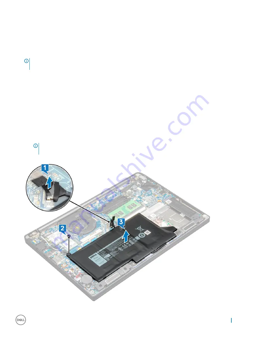
To remove the battery:

a Disconnect the battery cable from the connector on the system board [1].
b Remove the M2.0 x 5.0 screw that secures the battery to the computer [2].

NOTE: 

A 3-cell battery has a single screw, and a 4-cell battery has two screws. Hence, the image displayed below is a 

3-cell battery.

c Lift the battery from the system [3].

Removing and installing components

11

Содержание Latitude 7290

Страница 1: ...Latitude 7290 Owner s Manual Regulatory Model P28S Regulatory Type P28S002 ...

Страница 2: ... to hardware or loss of data and tells you how to avoid the problem WARNING A WARNING indicates a potential for property damage personal injury or death Copyright 2018 Dell Inc or its subsidiaries All rights reserved Dell EMC and other trademarks are trademarks of Dell Inc or its subsidiaries Other trademarks may be trademarks of their respective owners 2018 01 Rev A00 ...

Страница 3: ... advanced power management features Unplugging pressing and holding the power button for 15 seconds should discharge residual power in the system board notebooks Bonding Bonding is a method for connecting two or more grounding conductors to the same electrical potential This is done through the use of a field service electrostatic discharge ESD kit When connecting a bonding wire ensure that it is ...

Страница 4: ...and bonding wire can be either directly connected between your wrist and bare metal on the hardware if the ESD mat is not required or connected to the anti static mat to protect hardware that is temporarily placed on the mat The physical connection of the wrist strap and bonding wire between your skin the ESD mat and the hardware is known as bonding Use only Field Service kits with a wrist strap m...

Страница 5: ...uter if available CAUTION If your computer has an RJ45 port disconnect the network cable by first unplugging the cable from your computer 5 Disconnect your computer and all attached devices from their electrical outlets 6 Open the display 7 Press and hold the power button for few seconds to ground the system board CAUTION To guard against electrical shock unplug your computer from the electrical o...

Страница 6: ...at sink LED board Touchpad buttons board Power connector port Display Assembly Display Bezel Display hinge Display panel Camera System board Keyboard Palm rest Recommended tools The procedures in this document require the following tools Phillips 0 screwdriver Phillips 1 screwdriver Plastic scribe NOTE The 0 screw driver is for screws 0 1 and the 1 screw driver is for screws 2 4 2 6 Removing and i...

Страница 7: ... Heat sink module 4 System fan 2 Speaker 4 WWAN card 1 WLAN card 1 Power connector port 1 ESD bracket 1 EDP bracket 2 LED board 1 Smart card reader cage 2 Display hinge 6 Keyboard support plate 19 5 Keyboard 5 System board 8 Memory module bracket 1 LCD cover 4 2 Touchpad button 2 Fingerprint 1 USB Type B bracket 2 Thermal module 4 Thermal Fan 2 SSD holder 1 Battery 2 Removing and installing compon...

Страница 8: ...SIM card from the SIM card tray Replacing SIM card 1 Insert a paperclip or a SIM card removal tool into the pinhole on the SIM card tray 2 Use a scribe to pull the SIM card tray 3 Place on the SIM card on the tray 4 Insert the SIM card tray into the slot Removing dummy SIM card tray For models shipped with a WWAN card the SIM card tray must first be removed from the system before removing the syst...

Страница 9: ...ase the base cover a Loosen the eight M2 5 x 6 0 captive screws that secure the base cover to the system 1 Remember Exercise caution when loosening the screws Angle the screw driver to match the head of the screw to avoid a possible stripped screw head b Use a plastic scribe to release the base cover from the edge 2 Removing and installing components 9 ...

Страница 10: ...3 Lift the base cover from the system 10 Removing and installing components ...

Страница 11: ...tripped screw head 4 Follow the procedure in After working inside your computer Battery Removing battery 1 Follow the procedure in Before working inside your computer 2 Remove the base cover 3 To remove the battery a Disconnect the battery cable from the connector on the system board 1 b Remove the M2 0 x 5 0 screw that secures the battery to the computer 2 NOTE A 3 cell battery has a single screw...

Страница 12: ...ll battery 3 cell has a single screw a larger battery 4 cell has two screws 4 Install the base cover 5 Follow the procedure in After working inside your computer PCIe solid state drive Removing PCIe SSD 1 Follow the procedure in Before working inside your computer 2 Remove the following components a base cover b battery 3 To remove the PCIe solid state drive SSD a Loosen the two M2 0 x 3 0 captive...

Страница 13: ...rely with the tab on the palm rest 3 Tighten the two M2 0 x 3 0 screws to secure the PCIe SSD card to the SSD bracket 4 Install the following components battery base cover 5 Follow the procedure in After working inside your computer Speaker Removing speaker module 1 Follow the procedure in Before working inside your computer 2 Remove the a base cover b battery Removing and installing components 13...

Страница 14: ...tor Do not pull the cable as it may result in breakage b Un route the speaker cable from the routing clips 2 c Remove the tape that secures the speaker cables to the touchpad board 3 4 To remove the speaker module a Remove the two M2 0 x 3 0 screws that secure the speaker module to the system 1 NOTE Refer the speaker screw list 14 Removing and installing components ...

Страница 15: ... Install the a battery b base cover 6 Follow the procedure in After working inside your computer Coin cell battery Removing the coin cell battery 1 Follow the procedure in Before working inside your computer 2 Remove the a base cover b battery 3 To remove the coin cell battery a Disconnect the coin cell battery cable from the connector on the system board 1 NOTE You must un route the coin cell bat...

Страница 16: ... base cover 5 Follow the procedure in After working inside your computer WWAN card Removing WWAN card 1 Follow the procedure in Before working inside your computer 2 Remove the following components a base cover b battery 3 To remove the WWAN card a Remove the M2 0 x 3 0 screw that secures the WWAN bracket to the WWAN card 1 b Lift the WWAN bracket that secures the WWAN card 2 c Disconnect the WWAN...

Страница 17: ...uter 4 Install the a battery b base cover 5 Follow the procedure in After working inside your computer NOTE The IMEI number can also be found on the WWAN card WLAN card Removing WLAN card 1 Follow the procedure in Before working inside your computer 2 Remove the a base cover b battery 3 To remove the WLAN card a Remove the M2 0 x 3 0 screw that secures the metal bracket to the WLAN card 1 Removing...

Страница 18: ... to the connectors on the WLAN card 3 Place the metal bracket and tighten the M2 0 x 3 0 screw to secure it to the WLAN card 4 Install the following a battery b base cover 5 Follow the procedure in After working inside your computer Memory modules Removing memory module 1 Follow the procedure in Before working inside your computer 2 Remove the following a base cover b battery 3 To remove the memor...

Страница 19: ...l the following a battery b base cover 3 Follow the procedures in After working inside your computer Heat sink Removing heat sink assembly Heat sink assembly comprises of heat sink and the system fan 1 Follow the procedure in Before working inside your computer 2 Remove the following a base cover b battery 3 To remove the heat sink assembly NOTE To identify the number of screws see the screw list ...

Страница 20: ...Align the heat sink assembly with screw holders on the system board 2 Replace the M2 0 x 3 0 screws to secure the heat sink assembly to the system board NOTE Replace the screws in the order of the callout numbers 1 2 3 4 as indicated on the heat sink 3 Connect the fan cable to the connector on the system board 4 Install the following a battery b base cover 5 Follow the procedure in After working i...

Страница 21: ...the LED cable b Remove the M2 0 x 3 0 screw that secures the LED board to the system 2 c Lift the LED board from the system 3 Installing LED board 1 Insert the LED board into the slot on the computer 2 Replace the M2 0 x 3 0 screw to secure the LED board 3 Connect the LED cable to the LED board 4 Install the following a speaker b battery c base cover 5 Follow the procedure in After working inside ...

Страница 22: ...chpad buttons board a Disconnect the touchpad buttons board cable from the touchpad board 1 b Lift the speaker cable that is affixed to the computer 2 to reveal the touchpad buttons board 4 Remove M2 0 x 2 5 screws that secure the touchpad buttons board 1 To identify the screws see screw list 5 Lift the touchpad buttons board from the system 2 22 Removing and installing components ...

Страница 23: ...d cable to the connector on the touchpad board 4 Install the a speaker b battery c base cover 5 Follow the procedure in After working inside your computer Power connector port Removing power connector port 1 Follow the procedure in Before working inside your computer 2 Remove the following a base cover b battery 3 To remove the power connector port a Disconnect the power connector port cable from ...

Страница 24: ... Install the power connector port into the slot on the system 2 Place the metal bracket on the power connector port 3 Replace the M2 0 x 3 0 screw to secure the power connector port to the system 4 Connect the power connector port cable to the connector on the system board 5 Install the following a battery b base cover 6 Follow the procedure in After working inside your computer Display Assembly R...

Страница 25: ...Lift the eDP bracket from the eDP cable 3 d Lift the eDP cable to disconnect it from the connector on the system board 4 e Un route the eDP cable from the routing channel 5 4 To remove the display assembly a Open the display of the computer and lay it on a flat surface at 180 degree angle b Remove the six M2 5 x 4 0 screws that secure the display hinge to the display assembly 1 c Lift the display ...

Страница 26: ...pes to secure the eDP cable display cable to the system board 6 Connect the eDP cable to the connector on the system board 7 Install the eDP metal bracket on the eDP cable and tighten the M2 0 x 3 0 screws 8 Route the WLAN and WWAN cables through the routing channels 9 Install the a WLAN card b WWAN card c battery d base cover 10 Follow the procedure in After working inside your computer Display B...

Страница 27: ...from the display assembly Installing display bezel NOTE The display bezel installation procedure is applicable only for non touch systems 1 Place the display bezel on the display assembly 2 Press the edges of the display bezel until it clicks onto the display assembly NOTE Adhesive is used to secure the display bezel to the display panel 3 Install the a display assembly b WLAN card c WWAN card d b...

Страница 28: ...play assembly 3 Slide and remove the display hinge cap from the display panel Installing the display hinge cap 1 Place the display hinge cap on the slot and slide it back to fit on the display assembly 2 Install the a display assembly b WLAN card c WWAN card d battery e base cover 3 Follow the procedure in After working inside your computer Display panel 28 Removing and installing components ...

Страница 29: ... Remove the two M2 0 x 3 0 screws on the panel 1 b Slide the display panel away from the system and flip the display panel over 2 c Peel off the display connector adhesive strip from the display panel 1 d Peel off the mylar tape securing the display cable on the back of the display panel 2 e Lift the metal tab and disconnect the display cable from the back of the display panel 3 4 Removing and ins...

Страница 30: ...f Remove the display panel 30 Removing and installing components ...

Страница 31: ...r working inside your computer Camera Removing camera The removal procedure of the camera is only for a touch display 1 Follow the procedure in Before working inside your computer 2 Remove the following a base cover b battery c WLAN card d WWAN card e display assembly 3 To remove the camera module a Peel off the two pieces of conductive tape covering the camera module 1 NOTE The conductive tape is...

Страница 32: ... camera cable 2 Insert the camera module into the slot on the display assembly 3 Affix the tape securing the camera module 4 Install the following a display bezel b display assembly c WLAN card d WWAN card e battery f base cover 5 Follow the procedure in After working inside your computer 32 Removing and installing components ...

Страница 33: ...assembly 2 To identify the screws seescrew list 3 To disconnect the eDP cable NOTE If your system is shipped with an IR camera then the IR cable must be disconnected The IR cable is located beneath the eDP cable connector a Un route the WLAN and WWAN cables from the routing channels 1 b Remove the two M2 0 x 3 0 screws that secures the eDP cable 2 c Remove the eDP cable bracket 3 d Disconnect the ...

Страница 34: ...onnector port cables use a plastic scribe to release the cables from the connectors Do not pull the cable as it may result in breakage a speaker cable 1 b LED board cable 2 c coin cell battery cable 3 d touchpad cable and USH board cable 4 e power connector port 5 34 Removing and installing components ...

Страница 35: ... the memory module bracket a Remove the two M2 0 x 3 0 screws that secure memory module bracket to the system board 1 b Lift the memory module bracket from the system board 2 Removing and installing components 35 ...

Страница 36: ...move the USB Type C bracket Image does not display the USB Type C bracket removal b Remove the eight M2 0 x 5 0 screws that secure the system board 1 c Lift the system board away from the system 2 36 Removing and installing components ...

Страница 37: ...technicians must place the system board on an ESD mat to avoid damage Installing system board 1 Align the system board with the screw holders on the system 2 Replace the M2 0 x 5 0 screws to secure the system board to the system 3 Connect the speaker LED board coin cell battery touchpad and USH cables and power connector cables to the connectors on the system board 4 Connect the eDP cable to the c...

Страница 38: ...ory module f battery g base cover h dummy SIM card tray i SIM card 8 Follow the procedure in After working inside your computer Keyboard Removing keyboard assembly NOTE The keyboard and the keyboard tray together are called the keyboard assembly 1 Follow the procedure in Before working inside your computer 2 Remove a base cover b battery c memory module d PCIe SSD e WLAN card f WWAN card g heat si...

Страница 39: ... the keyboard assembly NOTE To identify the screws see screw list a Remove the 18 M2 0 x 2 5 screws that secure the keyboard 1 b Lift the keyboard assembly from the chassis 2 Removing and installing components 39 ...

Страница 40: ...yboard tray 2 Tighten the M2 0 x 2 0 screws to secure the keyboard to the keyboard tray 3 Install the keyboard assembly Installing keyboard assembly NOTE The keyboard and the keyboard tray together are called the keyboard assembly 1 Align the keyboard assembly with the screw holders on the computer 2 Tighten the M2 0 x 2 5 screws that secure the keyboard to the chassis 3 Connect the keyboard cable...

Страница 41: ...er working inside your computer Palm rest Replacing palm rest 1 Follow the procedure in Before working inside your computer 2 Remove the a base cover b battery c memory module d PCIe SSD e WLAN card f WWAN card g heat sink assembly h system board i power connector port j coin cell battery k speaker Removing and installing components 41 ...

Страница 42: ...t 4 Install the a speaker b coin cell battery c power connector port d system board e heat sink f WLAN card g WWAN card h PCIe SSD card i memory module j battery k base cover 5 Follow the procedure in After working inside your computer 42 Removing and installing components ...

Страница 43: ...requires 1 5 volts of electrical power to operate DDR4 also supports a new deep power down mode that allows the host device to go into standby without needing to refresh its memory Deep power down mode is expected to reduce standby power consumption by 40 to 50 percent DDR4 Details There are subtle differences between DDR3 and DDR4 memory modules as listed below Key notch difference The key notch ...

Страница 44: ...gital TV DTV The intended applications for HDMI TVs and DVD players The primary advantage is cable reduction and content protection provisions HDMI supports standard enhanced or high definition video plus multichannel digital audio on a single cable NOTE The HDMI 1 4 will provide 5 1 channel audio support HDMI 1 4 Features HDMI Ethernet Channel Adds high speed networking to an HDMI link allowing u...

Страница 45: ...ionality USB features Universal Serial Bus or USB was introduced in 1996 It dramatically simplified the connection between host computers and peripheral devices like mice keyboards external drivers and printers Let s take a quick look on the USB evolution referencing to the table below Table 2 USB evolution Type Data Transfer Rate Category Introduction Year USB 3 0 USB 3 1 Gen 1 5 Gbps Super Speed...

Страница 46: ...meras etc USB 2 0 may not be fast enough Furthermore no USB 2 0 connection could ever come close to the 480Mbps theoretical maximum throughput making data transfer at around 320Mbps 40MB s the actual real world maximum Similarly USB 3 0 USB 3 1 Gen 1 connections will never achieve 4 8Gbps We will likely see a real world maximum rate of 400MB s with overheads At this speed USB 3 0 USB 3 1 Gen 1 is ...

Страница 47: ... C is a new tiny physical connector The connector itself can support various exciting new USB standard like USB 3 1 and USB power delivery USB PD Alternate Mode USB Type C is a new connector standard that s very small It s about a third the size of an old USB Type A plug This is a single connector standard that every device should be able to use USB Type C ports can support a variety of different ...

Страница 48: ...nderbolt 3 1 Thunderbolt 1 and Thunderbolt 2 using a miniDP connector 2 Thunderbolt 3 using a USB Type C connector Thunderbolt 3 over USB Type C Thunderbolt 3 brings Thunderbolt to USB Type C at speeds up to 40 Gbps creating one compact port that does it all delivering the fastest most versatile connection to any dock display or data device like an external hard drive Thunderbolt 3 uses a USB Type...

Страница 49: ...el Kaby Lake U R Integrated in the processor DRAM bus width Flash EPROM PCIe bus External Bus Frequency Operating System Microsoft Windows 10 Home Microsoft Windows 10 Pro 64 bit Ubuntu Memory DDR4 2400 SDRAM operates at 2133 with Intel 7th Gen DDR4 2400 SDRAM operates at 2400 with Intel 8th Gen One DIMM slot up to 16 GB Chipset Intel Kaby Lake U R Integrated in the processor Video Intel HD Graphi...

Страница 50: ...are Authentication Bundle 1 FIPS 201 Contacted Smart Card with Control Vault 2 0 Advanced Authentication with FIPS 140 2 Level 3 Certification Optional Hardware Authentication Bundle 2 Touch Fingerprint Reader FIPS 201 Contacted Smart Card Contactless Smart Card NFC Control Vault 2 0 Advanced Authentication with FIPS 140 2 Level 3 Certification Docking options Dell Dock WD15 optional Dell Thunderb...

Страница 51: ...o 104 F Temperature range Non Operating 40 C to 70 C 40 F to 158 F Communications Network adapter 10 100 1000 Mb s Ethernet RJ 45 Wireless Internal wireless local area network WLAN wireless wide area network WWAN Ports Slots and Chassis HDMI 1 4 1 Universal Jack MultiMedia card reader SD 4 0 uSIM external 2 x USB 3 1 Gen1 one with PowerShare DisplayPort over USB Type C optional Thunderbolt 3 1 RJ4...

Страница 52: ...rating 15 2 m to 3048 m 50 to 10 000 ft 0 C to 35 C Non operating 15 24 m to 10 668 m 50 ft to 35 000 ft Airborne contaminant level G2 or lower as defined by ISA S71 04 1985 Display specifications in detail Table 4 12 5 inches 16 9 AG HD WLED 200 nits eDP 1 2 TN HD CAM Mic WLAN capable Mag Alloy back Non Touch Feature Specification Type HD Anti Glare Luminance typical 200 nits Dimensions Active Ar...

Страница 53: ...Vertical View Angle 10 30 degrees Pixel Pitch 0 2025 mm Power Consumption maximum 2 9 W Table 6 12 5 inches 16 9 AG HD WLED 200 nits eDP 1 2 TN Mic only WLAN capable Mag Alloy back Non Touch Feature Specification Type HD Anti Glare Luminance typical 200 nits Dimensions Active Area Height 155 52mm Width 276 62mm Diagonal 12 5 inch Native Resolution 1366x768 Megapixels 1 05 Pixels per Inch PPI 125 C...

Страница 54: ...n F4 Mic Mute Fn F5 Num Lock Fn F6 Scroll Lock Fn F7 optional Increase keyboard back light brightness Fn F8 Display Toggle Win P Fn F9 Search Fn F10 Increase keyboard back light brightness Fn F11 Print screen Fn F12 Insert Fn Home WLAN on off Fn End Sleep Fn up arrow Increase display brightness Fn down arrow Decrease display brightness 54 System specifications ...

Страница 55: ...anagement screen options POST behavior screen options Manageability Virtualization support screen options Wireless screen options Maintenance screen options System logs screen options System and setup password Updating the BIOS in Windows Boot menu Press F12 when the Dell logo appears to initiate a one time boot menu with a list of the valid boot devices for the system Diagnostics and BIOS Setup o...

Страница 56: ...on System Information This section lists the primary hardware features of your computer System Information Displays BIOS Version Service Tag Asset Tag Ownership Tag Ownership Date Manufacture Date Express Service Code the Signed Firmware update enabled by default Memory Information Displays Memory Installed Memory Available Memory Speed Memory Channels Mode Memory Technology DIMM ASize DIMM B Size...

Страница 57: ...ATA hard drive controller The options are Disabled AHCI RAID On This option is enabled by default Drives Allows you to configure the SATA drives on board All drives are enabled by default The options are SATA 2 M 2 PCI e SSD 0 SMART Reporting This field controls whether hard drive errors for integrated drives are reported during system startup This technology is part of the SMART Self Monitoring A...

Страница 58: ...0 The options are Disabled Dim Bright enabled by default Keyboard Backlight with AC The Keyboard Backlight with AC option does not affect the main keyboard illumination feature Keyboard Illumination will continue to support the various illumination levels This field has an effect when the backlight is enabled This option is enabled by default Keyboard Backlight Timeout on AC The Keyboard Backlight...

Страница 59: ...must set the admin password before you set the system or hard drive password Deleting the admin password automatically deletes the system password and the hard drive password NOTE Successful password changes take effect immediately Default setting Not set System Password Allows you to set change or delete the system password NOTE Successful password changes take effect immediately Default setting ...

Страница 60: ... enabled by default TPM 2 0 Security Allows you to enable the Trusted Platform Module TPM during POST The options are UEFI capsule Firmware updates enabled by default TPM On enabled by default Clear PPI Bypass for Enable Commands PPI Bypass for Disabled Commands Attestation enable enabled by default Key storage enable enabled by default SHA 256 enabled by default Disabled Enabled enabled by defaul...

Страница 61: ... Custom Mode option is disabled by default The options are PK enabled by default KEK db dbx If you enable the Custom Mode the relevant options for PK KEK db and dbx appear The options are Save to File Saves the key to a user selected file Replace from File Replaces the current key with a key from a user selected file Append from File Adds a key to the current database from a user selected file Del...

Страница 62: ...upport one core is enabled Enable Multi Core Support Default setting The option is enabled Intel SpeedStep Allows you to enable or disable the Intel SpeedStep feature Enable Intel SpeedStep Default setting The option is enabled C States Control Allows you to enable or disable the additional processor sleep states C states Default setting The option is enabled Intel TurboBoost Allows you to enable ...

Страница 63: ...Support Wake on Dell USB C dock Default setting The option is disabled Wireless Radio Control Allows you to enable or disable the feature that automatically switches from wired or wireless networks without depending on the physical connection Control WLAN Radio Control WWAN Radio Default setting The options are disabled Wake on WLAN Allows you to enable or disable the feature that powers on the co...

Страница 64: ...selected you can also configure Custom Charge Start and Custom Charge Stop NOTE All charging mode may not be available for all the batteries To enable this option disable the Advanced Battery Charge Configuration option Type C connector power 7 5 Watts 15 Watts enabled by default POST behavior screen options Option Description Adapter Warnings Allows you to enable or disable the system setup BIOS ...

Страница 65: ...e Full Screen Logo not enabled Warnings and errors Prompt on warnings and errors enabled by default Continue on warnings Continue on warnings and errors Manageability Option Description USB provision Enable USB provision is not selected by default MEBX Hotkey enabled by default Allows you to specify whether the MEBx Hotkey function should enable during the system boot Disabled Enabled Default sett...

Страница 66: ...on Description Service Tag Displays the Service Tag of your computer Asset Tag Allows you to create a system asset tag if an asset tag is not already set This option is not set by default BIOS Downgrade This controls flashing of the system firmware to previous revisions Option Allow BIOS downgrade is enabled by default Data Wipe This field allows users to erase the data securely from all internal ...

Страница 67: ...r System Setup screen select Security and press Enter The Security screen is displayed 2 Select System Password and create a password in the Enter the new password field Use the following guidelines to assign the system password A password can have up to 32 characters The password can contain the numbers 0 through 9 Only lower case letters are valid upper case letters are not allowed Only the foll...

Страница 68: ...rs 6 Click Get drivers and click Drivers and Downloads The Drivers and Downloads section opens 7 Click Find it myself 8 Click BIOS to view the BIOS versions 9 Identify the latest BIOS file and click Download 10 Select your preferred download method in the Please select your download method below window click Download File The File Download window appears 11 Click Save to save the file on your comp...

Страница 69: ... Update Screen Updating the Dell BIOS in Linux and Ubuntu environments If you want to update the system BIOS in a Linux environment such as Ubuntu see http www dell com support article us en 19 SLN171755 updating the dell bios in linux and ubuntu environments Flashing the BIOS from the F12 One Time boot menu Updating your system BIOS using a BIOS update exe file copied to a FAT32 USB key and booti...

Страница 70: ...date flash process from the F12 menu CAUTION Do not power off the system during the BIOS update process Powering off the system could make the system fail to boot 1 From a power off state insert the USB key where you copied the flash into a USB port of the system 2 Power on the system and press the F12 key to access the One Time Boot Menu Highlight BIOS Flash Update using the arrow keys then press...

Страница 71: ...5 Once the file is selected it will show in the file selection box and you can click the OK button to continue 6 Click the Begin Flash Update button System setup 71 ...

Страница 72: ...ecute the system will reboot and then the BIOS flash will start and a progress bar will show the progress of the flash Depending on the changes included in the update the progress bar may go from zero to 100 multiple times and the flash process could take as long as 10 minutes Generally this process takes two to three minutes 72 System setup ...

Страница 73: ...9 Once complete the system will reboot and the BIOS update process is completed System setup 73 ...

Страница 74: ... bit Other Ubuntu 16 04 LTS SP1 64 bit NeoKylin v6 0 64 bit Downloading drivers 1 Turn on the notebook 2 Go to Dell com support 3 Click Product Support enter the Service Tag of your notebook and then click Submit NOTE If you do not have the Service Tag use the auto detect feature or manually browse for your notebook model 4 Click Drivers and Downloads 5 Select the operating system installed on you...

Страница 75: ...Chipset driver Verify if the Intel chipset and Intel Management Engine Interface drivers are already installed in the system Software 75 ...

Страница 76: ...76 Software ...

Страница 77: ... in the system Network driver This system comes with both LAN and WiFi drivers and is able to detect the LAN and WiFi without going through the drivers installation USB driver Verify if the USB drivers are already installed in the system Storage driver Verify if the storage controller drivers are installed in the system Software 77 ...

Страница 78: ...components in the Device Manager Security device driver Verify if the security device driver is installed in the system HID Verify if the HID driver is installed in the system Image device driver Verify if the image device driver is installed in the system 78 Software ...

Страница 79: ...system from a power off state only if it is connected to AC power Press and hold the power button for 25 seconds The system RTC reset occurs after you release the power button NOTE If AC power is disconnected from the system during the process or the power button is held longer than 40 seconds the RTC reset process is aborted The RTC reset will reset the BIOS to Defaults un provision Intel vPro an...

Страница 80: ... service options Availability varies by country and product and some services may not be available in your area To contact Dell for sales technical support or customer service issues 1 Go to Dell com support 2 Select your support category 3 Verify your country or region in the Choose a Country Region drop down list at the bottom of the page 4 Select the appropriate service or support link based on...

Отзывы: