background image

Latitude 7220EX Rugged Extreme Tablet

Service Manual

Regulatory Model: T03H
Regulatory Type: T03H004
August 2021
Rev. A02

Содержание Latitude 7220EX

Страница 1: ...Latitude 7220EX Rugged Extreme Tablet Service Manual Regulatory Model T03H Regulatory Type T03H004 August 2021 Rev A02 ...

Страница 2: ...tial damage to hardware or loss of data and tells you how to avoid the problem WARNING A WARNING indicates a potential for property damage personal injury or death 2019 2020 Dell Inc or its subsidiaries All rights reserved Dell EMC and other trademarks are trademarks of Dell Inc or its subsidiaries Other trademarks may be trademarks of their respective owners ...

Страница 3: ...de 13 ESD field service kit 13 After working inside the tablet 14 Recommended tools 14 Screw list 15 Customer Replaceable Units CRU and Field Replaceable Units FRU list 16 Disassembly and reassembly 17 Batteries cover assembly 18 System cover 21 Batteries 24 Subscriber Identification Module SIM card 27 Stylus 28 Display assembly 30 SSD Heat sink 38 System fan 40 Solid state drive 42 WLAN card 44 W...

Страница 4: ... the F12 One Time boot menu 82 System and setup password 85 Assigning a system setup password 85 Deleting or changing an existing system setup password 86 Chapter 5 Software 87 Drivers and downloads 87 Chapter 6 Troubleshooting 88 Handling swollen Lithium ion batteries 88 Enhanced Pre Boot System Assessment ePSA diagnostics 89 Running the ePSA diagnostics 89 Built in self test BIST 89 M BIST 89 LC...

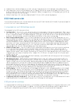
Страница 5: ...tions that came with the product CAUTION To avoid electrostatic discharge ground yourself by using a wrist grounding strap or by periodically touching an unpainted metal surface simultaneously as touching a connector on the back of the tablet CAUTION Handle components and cards with care Do not touch the components or contacts on a card Hold a card by its edges or by its metal mounting bracket Hol...

Страница 6: ...protection ESD is a major concern when you handle electronic components especially sensitive components such as expansion cards processors memory DIMMs and system boards Very slight charges can damage circuits in ways that may not be obvious such as intermittent problems or a shortened product life span As the industry pushes for lower power requirements and increased density ESD protection is an ...

Страница 7: ...gional office to find out if they have one To perform the test plug the wrist strap s bonding wire into the tester while it is strapped to your wrist and push the button to test A green LED is lit if the test is successful a red LED is lit and an alarm sounds if the test fails Insulator Elements It is critical to keep ESD sensitive devices such as plastic heat sink casings away from internal parts...

Страница 8: ...mage to the tablet use only the battery that is designed for this particular Dell tablet Do not use batteries that are designed for other Dell tablets Steps 1 Connect any external devices such as a mobile keyboard or a docking station and replace any cards such as an ExpressCard 2 Connect your tablet and all attached devices to their electrical outlets 3 Turn on your tablet 8 Working on your table...

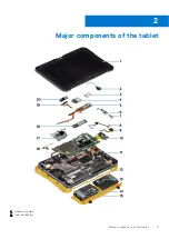
Страница 9: ...Major components of the tablet 1 Display assembly 2 Coin cell battery 2 Major components of the tablet 9 ...

Страница 10: ...the back 15 Battery cover assembly 16 Microphone assembly circuit board 17 System fan 18 Solid state drive 19 Front camera cable 20 Front camera cover NOTE Dell provides a list of components and their part numbers for the original system configuration purchased These parts are available according to warranty coverages purchased by the customer Contact your Dell sales representative for purchase op...

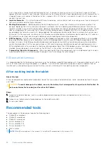
Страница 11: ...mple repairs as authorized in your product documentation or as directed by the online or telephone service and support team Damage due to servicing that is not authorized by Dell is not covered by your warranty Read and follow the safety instructions that came with the product CAUTION To avoid electrostatic discharge ground yourself by using a wrist grounding strap or by periodically touching an u...

Страница 12: ...component carefully place the removed component on an antistatic mat Wear shoes with nonconductive rubber soles to reduce the chance of getting electrocuted Bonding Bonding is a method for connecting two or more grounding conductors to the same electrical potential This is done by using a field service electrostatic discharge ESD kit When connecting a bonding wire ensure that it is connected to ba...

Страница 13: ...nt with appropriate Dell power adapters WARNING The I O and battery bay covers must be closed with both screws tightened before the system is exposed to a potentially explosive environment WARNING Do not remove the battery or access the I O ports while the system is exposed to a potentially explosive environment WARNING Do not connect external devices to any of the system ports while the system is...

Страница 14: ...he same foam packing material should be used in the original box that the new part arrived in ESD sensitive devices should be removed from packaging only at an ESD protected work surface and parts should never be placed on top of the ESD bag because only the inside of the bag is shielded Always place parts in your hand on the ESD mat in the system or inside an anti static bag Transporting Sensitiv...

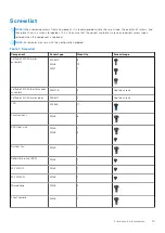
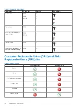
Страница 15: ...w color may vary with the configuration ordered Table 1 Screw list Component Screw type Quantity Screw image Latitude 7220EX armor assembly M2 5x10 M2x6 M4x7 8 12 1 Latitude 7220EX battery cover assembly M4x11 5 2 Captive screws Latitude 7220EX armor door M3 5x11 2 Captive screws LCD M2 5x5 11 Function keys M2x5 6 SSD Heat sink M2x5 M2x3 1 3 System fan M2x5 4 Solid state drive SSD M2x3 1 M 2 WLAN ...

Страница 16: ...nd power connector port M2x5 M1 6x5 6 2 Docking Board M2x5 5 Smart card reader and wireless passthrough daughterboard M2x5 10 Customer Replaceable Units CRU and Field Replaceable Units FRU list Table 2 CRU FRU list CRU component FRU component Battery Stylus Batteries cover assembly System cover SIM card Camera shutter 16 Field service information ...

Страница 17: ...m base assembly Front camera Rear camera M 2 WLAN card M 2 WWAN card M 2 SSD Power button assembly Microphone Coin cell battery System board Disassembly and reassembly NOTE The images in this document may differ from your computer depending on the configuration you ordered Field service information 17 ...

Страница 18: ... assembly Prerequisites 1 Follow the procedure in before working inside the tablet About this task The figure indicates the location of the batteries cover assembly and provides a visual representation of the removal procedure 18 Field service information ...

Страница 19: ...e chassis 4 Remove the battery cover assembly from the tablet Installing the batteries cover assembly Prerequisites If you are replacing a component remove the existing component before performing the installation procedure About this task The figure indicates the location of the batteries cover assembly and provides a visual representation of the installation procedure Field service information 1...

Страница 20: ...20 Field service information ...

Страница 21: ...5 captive screws to its initial position Next steps 1 Follow the procedure in after working inside the tablet System cover Removing the system cover Prerequisites 1 Follow the procedure in before working inside the tablet 2 Remove the batteries cover assembly 3 Remove the stylus About this task The figure indicates the location of the system cover and provides a visual representation of the remova...

Страница 22: ...22 Field service information ...

Страница 23: ...osen the two M4x11 5 captive screws that secure the side cover assembly to the chassis and remove the system cover assembly from the tablet Installing the system cover Prerequisites If you are replacing a component remove the existing component before performing the installation procedure About this task The figure indicates the location of the system cover and provides a visual representation of ...

Страница 24: ...ng inside the tablet Batteries Lithium ion battery precautions CAUTION Exercise caution when handling Lithium ion batteries Discharge the battery completely before removing it Disconnect the AC power adapter from the system and operate the computer solely on battery power the battery is fully discharged when the computer no longer turns on when the power button is pressed Do not crush drop mutilat...

Страница 25: ...authorized Dell partners and resellers Swollen batteries should not be used and should be replaced and disposed properly For guidelines on how to handle and replace swollen Lithium ion batteries see Handling swollen Lithium ion batteries Removing the batteries Prerequisites 1 Follow the procedure in before working inside the tablet 2 Remove the batteries cover assembly NOTE This tablet can accommo...

Страница 26: ...ure About this task NOTE This tablet can accommodate two hot swap capable batteries Primary and optional The installation procedure of the primary and optional battery are identical The figure indicates the location of the battery and provides a visual representation of the installation procedure Steps 1 Align the pins on the battery with the connector on the tablet NOTE Ensure that the metal pin ...

Страница 27: ...re working inside the tablet 2 Remove the batteries cover assembly 3 Remove the batteries About this task The figure indicates the location of the uSIM and provides a visual representation of the removal procedure Steps 1 Open the uSIM slot cap 2 Press the uSIM card and slide it out of the slot NOTE Use a flat pointed scribe to ease removing the SIM Inserting the uSIM Prerequisites If you are repl...

Страница 28: ...lot cap to initial state Next steps 1 Install the batteries 2 Install the battery cover assembly 3 Follow the procedure in after working inside the tablet Stylus Removing the stylus Prerequisites 1 Follow the procedure in before working inside the tablet About this task The figure indicates the location of the stylus and provides a visual representation of the removal procedure 28 Field service in...

Страница 29: ...us through the hole to remove the tether from the chassis Installing the stylus Prerequisites If you are replacing a component remove the existing component before performing the installation procedure About this task The figure indicates the location of the stylus and provides a visual representation of the installation procedure Field service information 29 ...

Страница 30: ... Removing the display assembly Prerequisites 1 Follow the procedure in before working inside the tablet 2 Remove the batteries cover assembly 3 Remove the system cover 4 Remove the batteries 5 Remove the stylus CAUTION Once removed the original display assembly cannot be reused To maintain IP20 rating a new display assembly must be installed About this task The figure indicates the location of the...

Страница 31: ...Field service information 31 ...

Страница 32: ...32 Field service information ...

Страница 33: ...the display assembly and to the clips that secure the display assembly to the chassis 4 Flip the LCD panel by an angle less than 90 NOTE Ensure not to flip more than 90 angle as the LCD panel ports and cables are connected to the system board and may damage the LCD cables 5 Remove the adhesive tape Using a plastic scribe lift the latch and disconnect the eDP cable from the connector on the system ...

Страница 34: ...nstalling the display assembly Prerequisites If you are replacing a component remove the existing component before performing the installation procedure About this task The figure indicates the location of the component and provides a visual representation of the installation procedure 34 Field service information ...

Страница 35: ...Field service information 35 ...

Страница 36: ...36 Field service information ...

Страница 37: ...latch Secure the connector with new adhesive tape 4 Align the LCD panel on the chassis 5 Press the edges of the display assembly to secure it to the chassis 6 Flip the tablet NOTE Ensure to place the tablet on a flat surface 7 Replace the 11 M2 5x5 screws that secure the display assembly to the chassis CAUTION The torque setting for this step is critical to maintain IP20 rating For all screws in t...

Страница 38: ...Remove the system cover 4 Remove the batteries 5 Remove the stylus 6 Remove the display assembly About this task The figure indicates the location of the heat sink and provides a visual representation of the removal procedure Steps 1 Remove the three M2X3 screws and M2X5 screw that secure the SSD heat sink to the system board 38 Field service information ...

Страница 39: ...k away from the system board Installing the SSD heat sink Prerequisites If you are replacing a component remove the existing component before performing the installation procedure About this task The figure indicates the location of the SSD heat sink and provides a visual representation of the installation procedure Steps 1 Align the screws on the SSD heat sink with the screw holes on the system b...

Страница 40: ...ing inside the tablet System fan Removing the system fan Prerequisites 1 Follow the procedure in before working inside the tablet 2 Remove the batteries cover assembly 3 Remove the system cover 4 Remove the batteries 5 Remove the stylus 6 Remove the display assembly 7 Remove the SSD heat sink About this task The figure indicates the location of the system fan and provides a visual representation o...

Страница 41: ... system fan to the system board 4 Lift the system fan off the system board Installing the system fan Prerequisites If you are replacing a component remove the existing component before performing the installation procedure About this task The figure indicates the location of the system fan and provides a visual representation of the installation procedure Field service information 41 ...

Страница 42: ... cable through the routing guide on the system fan Next steps 1 Install the SSD heat sink 2 Install the display assembly 3 Install the stylus 4 Install the batteries 5 Install the system cover 6 Install the battery cover assembly 7 Follow the procedure in after working inside the tablet Solid state drive Removing the M 2 2280 solid state drive Prerequisites 1 Follow the procedure in before working...

Страница 43: ...screw that secures the solid state drive to the system board 2 Slide and remove the solid state drive from the solid state drive slot on the system board Installing the M 2 2280 solid state drive Prerequisites If you are replacing a component remove the existing component before performing the installation procedure About this task The following image indicates the location of the M 2 2280 solid s...

Страница 44: ... 5 Install the battery cover assembly 6 Follow the procedure in after working inside the tablet WLAN card Removing the WLAN card Prerequisites 1 Follow the procedure in before working inside the tablet 2 Remove the batteries cover assembly 3 Remove the system cover 4 Remove the batteries 5 Remove the stylus 6 Remove the display assembly About this task The figure indicates the location of the WLAN...

Страница 45: ...the antenna cables from the WLAN card 5 Slide and remove the WLAN card from the WLAN card slot Installing the WLAN card Prerequisites If you are replacing a component remove the existing component before performing the installation procedure About this task The figure indicates the location of the WLAN card and provides a visual representation of the installation procedure Field service informatio...

Страница 46: ...3 Connectors on the wireless card Antenna Cable Color Main white triangle White Auxiliary black triangle Black 3 Place the WLAN card bracket on the WLAN card 4 Replace the screw M2x3 to secure the WLAN card bracket to the WLAN card 5 Affix the adhesive tape to secure the antenna cables Next steps 1 Install the display assembly 2 Install the stylus 3 Install the batteries 4 Install the system cover...

Страница 47: ...low the procedure in before working inside the tablet 2 Remove the batteries cover assembly 3 Remove the system cover 4 Remove the batteries 5 Remove the stylus 6 Remove the display assembly About this task The figure indicates the location of the WWAN card and provides a visual representation of the removal procedure Field service information 47 ...

Страница 48: ...he WWAN card Prerequisites If you are replacing a component remove the existing component before performing the installation procedure About this task The figure indicates the location of the WWAN card and provides a visual representation of the installation procedure Steps 1 Slide the WWAN card at an angle into the WWAN card slot 2 Connect the antenna cables to the WWAN card The following table p...

Страница 49: ...lus 3 Install the batteries 4 Install the system cover 5 Install the battery cover assembly 6 Follow the procedure in after working inside the tablet Microphone Removing the microphone Prerequisites 1 Follow the procedure in before working inside the tablet 2 Remove the batteries cover assembly 3 Remove the system cover 4 Remove the batteries 5 Remove the stylus 6 Remove the display assembly About...

Страница 50: ...ne assembly 3 Release the microphone assembly and lift the microphone from the tablet chassis NOTE NEVER pull the microphone by the cable In case the circuit board is not released smoothly push from below the microphone circuit board by a plastic scribe Installing the microphone Prerequisites If you are replacing a component remove the existing component before performing the installation procedur...

Страница 51: ...e cable Next steps 1 Install the display assembly 2 Install the stylus 3 Install the batteries 4 Install the system cover 5 Install the battery cover assembly 6 Follow the procedure in after working inside the tablet Front camera Removing the front camera Prerequisites 1 Follow the procedure in before working inside the tablet 2 Remove the batteries cover assembly 3 Remove the system cover 4 Remov...

Страница 52: ...52 Field service information ...

Страница 53: ...edge to insert the plastic scribe in the gap 7 Disconnect the camera cable that secures the cable to the system board 8 Lift the lens case by an angle not more than 35 and push upward to release the camera lens case 9 Remove the camera circuit board away from the tablet chassis Installing the front camera Prerequisites If you are replacing a component remove the existing component before performin...

Страница 54: ...54 Field service information ...

Страница 55: ...ce the screw M2x3 to secure the front camera circuit board on the tablet chassis 7 Slide the lens shutter in the lens channel and push towards left 8 Replace the adhesive tape on the camera assembly and system board shield Next steps 1 Install the display assembly 2 Install the stylus 3 Install the batteries 4 Install the system cover 5 Install the battery cover assembly 6 Follow the procedure in ...

Страница 56: ...is task The figure indicates the location of the coin cell battery and provides a visual representation of the removal procedure Steps 1 Disconnect the coin cell battery cable from the system board 2 Move the fingerprint reader cable and microSD card cable over the coin cell battery 3 Peel the coin cell battery off the system board Installing the coin cell battery Prerequisites If you are replacin...

Страница 57: ...t on the system board 2 Place the fingerprint cable and microSD card cable on the coin cell battery 3 Connect the coin cell battery cable to the connector on the system board Next steps 1 Install the display assembly 2 Install the batteries 3 Install the system cover 4 Install the battery cover assembly 5 Follow the procedure in after working inside the tablet Field service information 57 ...

Страница 58: ...ystem cover 4 Remove the batteries 5 Remove the stylus 6 Remove the display assembly 7 Remove the SSD heat sink 8 Remove the system fan 9 Remove the solid state drive 10 Remove the WLAN 11 Remove the WWAN About this task The figure indicates the location of the system board and provides a visual representation of the removal procedure 58 Field service information ...

Страница 59: ...Field service information 59 ...

Страница 60: ...of the FPC cables is not stuck under the rubber grommet The FPC cables may get damaged when they are forcefully slid out when their pull tabs are still stuck under the rubber grommet 7 Peel the adhesive tape and remove the three M2x5 screws that secure the camera MIPI plate to the system board Remove the adhesive tape Disconnect the power adapter and rear camera flexible flat cable FFC from the sy...

Страница 61: ...About this task The figure indicates the location of the system board and provides a visual representation of the installation procedure Field service information 61 ...

Страница 62: ...62 Field service information ...

Страница 63: ...ard LTE main p sensor mic smartcard fingerprint reader microSD card NFC mini serial speaker right battery and left battery from the system board 6 As illustrated affix the adhesive tapes to the connectors on the system board 7 Route the GPS cable into the routing channel and connect it to the system board 8 Slide the antenna cable into the clip and connect the antenna cables to the system board 9 ...

Страница 64: ... drive 9 Remove the WLAN 10 Remove the WWAN 11 Remove the microphone 12 Remove the front camera 13 Remove the coin cell battery 14 Remove the system board About this task The figure indicates the location of the rear camera and provides a visual representation of the removal procedure Steps 1 Peel the copper adhesive tape and remove the three M2x5 screws that secure the rear camera circuit board o...

Страница 65: ...blet chassis 2 Replace copper adhesive tape and the three M2x5 screws to secure the rear camera circuit board to the chassis Next steps 1 Install the system board 2 Install the coin cell battery 3 Install the front camera 4 Install the microphone 5 Install the WWAN 6 Install the WLAN 7 Install the solid state drive 8 Install the system fan 9 Install the SSD heat sink 10 Install the display assembl...

Страница 66: ...wer connector DC in port and provides a visual representation of the removal procedure Steps 1 Disconnect the DC in cable from the connector and remove the M2x5 screw that secures the system board to the system chassis 2 Lift the latch and disconnect the micro serial port cable from the connector 3 Remove the four M2x5 screws and two M1 6x5 screws that secure the metal bracket to the system chassi...

Страница 67: ...ower connector DC in port and provides a visual representation of the installation procedure Steps 1 Insert the DC in port and micro serial port into the slot on the chassis 2 Replace the M2x5 screw that secures the DC in port and serial port to the system chassis and align the rubber grommet to slide in the channel 3 Align the metal brackets that secure the ports on the system chassis 4 Replace t...

Страница 68: ...screw that secures the system board to the system chassis Next steps 1 Install the display assembly 2 Install the batteries 3 Install the system cover 4 Install the battery cover assembly 5 Follow the procedure in after working inside the tablet 68 Field service information ...

Страница 69: ...tup password Boot menu Press and hold the Volume down key to access the BIOS Press and hold the Volume up key to access the one time boot menu with a list of the valid boot devices for the system Diagnostics and BIOS Setup options are also in this menu The devices that are listed on the boot menu depend on the bootable devices in the system This menu is useful when you are attempting to boot to a ...

Страница 70: ... screen System setup options NOTE Depending on the tablet and its installed devices the items listed in this section may or may not appear General options Table 5 General Option Description System Information Displays the following information System Information Displays BIOS Version Service Tag Asset Tag Ownership Tag Manufacture Date Ownership Date and the Express Service Code Memory Information...

Страница 71: ...oller for Enable USB Boot Support Enable External USB Port All the options are enabled by default Optimize USB selected by default Optimize GPS USB PowerShare This option configures the USB PowerShare feature behavior Enable USB PowerShare disabled by default This feature is intended to allow users to power or charge external devices such as phones and portable music players using the stored syste...

Страница 72: ...us illumination levels This field has an effect when the backlight is enabled The options are 5 sec 10 sec enabled by default 15 sec 30 sec 1 min 5 min 15 min Never RGB Keyboard Backlight The RGB keyboard backlight feature There are six available colors four preset colors white red green and blue and two user configurable colors White Enabled and Active Red Enabled Green Enabled Blue Enabled Custo...

Страница 73: ... of characters allowed for a administrative password and the system password The range of characters is between 4 and 32 Password Bypass This option lets you bypass the System Boot Password and the internal HDD password prompts during a system restart Disabled Always prompt for the system and internal HDD password when they are set This option is enabled by default Reboot Bypass Bypass the passwor...

Страница 74: ...ble Admin Setup Lockout Allows you to prevent users from entering Setup when Admin password is set This option is not set by default Master Password Lockout Allows you to disable master password support Hard Disk passwords need to be cleared before the settings can be changed This option is not set by default SMM Security Mitigation Allows you to enable or disable additional UEFI SMM Security Miti...

Страница 75: ... Option Description Intel SGX Enable This field specifies you to provide a secured environment for running code storing sensitive information in the context of the main OS Click one of the following options Disabled Enabled Software controlled Default Enclave Memory Size This option sets SGX Enclave Reserve Memory Size Click one of the following options 32 MB 64 MB 128 MB Default Performance Table...

Страница 76: ...sabled Every Day Weekdays Select Days Default setting Disabled USB Wake Support Allows you to enable USB devices to wake the system from Standby NOTE This feature is only functional when the AC power adapter is connected If the AC power adapter is removed during Standby the system setup removes power from all the USB ports to conserve battery power Enable Wake on Dell USB C Dock Wake on LAN Allows...

Страница 77: ...ble this option disable the Advanced Battery Charge Configuration option Dock Battery Charger Mode Allows you to select the charging mode for the battery The options are Standard enabled by default ExpressCharge The battery charges over a shorter time using Dell s fast charging technology Type C Connector Power This allows you to set the maximum power that can be drawn from the Type C connector Th...

Страница 78: ...ility Allows you to provision AMT and MEBx Hotkey function is enabled during the system boot Disabled Enabled by default Restrict MEBx Access USB Provision When enabled Intel AMT can be provisioned using the local provisioning file via a USB storage device Enable USB Provision disabled by default MEBX Hotkey Allows you to specify whether the MEBx Hotkey function should enable during the system boo...

Страница 79: ...WWAN Ant B Allows enabling disabling of WWAN GPS Ant B Allows enabling disabling of GPS Maintenance screen Option Description Service Tag Displays the Service Tag of your computer Asset Tag Allows you to create a system asset tag if an asset tag is not already set This option is not set by default BIOS Downgrade This controls flashing of the system firmware to previous revisions Option Allow BIOS ...

Страница 80: ...m errors SupportAssist OS Recovery This option is set by default About License Information It contains the Copyright information Updating the BIOS in Windows Prerequisites It is recommended to update your BIOS System Setup when you replace the system board or if an update is available About this task NOTE If BitLocker is enabled it must be suspended prior to updating the system BIOS and then re en...

Страница 81: ...r more information about this subject see Knowledge Article https www dell com support article sln153694 Updating your system BIOS using a USB flash drive About this task If the system cannot load into Windows but there is still a need to update the BIOS download the BIOS file using another system and save it to a bootable USB Flash Drive NOTE You will need to use a bootable USB flash drive Please...

Страница 82: ...n the F12 One Time Boot Menu can use this function Updating from the One Time Boot Menu To update your BIOS from the F12 One Time boot menu you will need USB key formatted to the FAT32 file system key does not have to be bootable BIOS executable file that you downloaded from the Dell Support website and copied to the root of the USB key AC power adapter connected to the system Functional system ba...

Страница 83: ...3 The Bios flash menu will open then click the Flash from file 4 Select external USB device System setup 83 ...

Страница 84: ...5 Once the file is selected Double click the flash target file then press submit 6 Click the Update BIOS then system will reboot to flash the BIOS 84 System setup ...

Страница 85: ...n your computer CAUTION Anyone can access the data stored on your computer if it is not locked and left unattended NOTE System and setup password feature is disabled Assigning a system setup password Prerequisites You can assign a new System or Admin Password only when the status is in Not Set About this task To enter the system setup press F2 immediately after a power on or re boot Steps 1 In the...

Страница 86: ...Setup password if the Password Status is Locked About this task To enter the System Setup press F2 immediately after a power on or reboot Steps 1 In the System BIOS or System Setup screen select System Security and press Enter The System Security screen is displayed 2 In the System Security screen verify that Password Status is Unlocked 3 Select System Password alter or delete the existing system ...

Страница 87: ... with instructions on how to install the drivers Topics Drivers and downloads Drivers and downloads When troubleshooting downloading or installing drivers it is recommended that you read the Dell Knowledge Based article Drivers and Downloads FAQ 000123347 5 Software 87 ...

Страница 88: ...the battery unplug the AC adapter from the system and operate the system only on battery power When the system will no longer power on when the power button is pressed the battery is fully discharged Do not crush drop mutilate or penetrate the battery with foreign objects Do not expose the battery to high temperatures or disassemble battery packs and cells Do not apply pressure to the surface of t...

Страница 89: ...ect the Diagnostics option 5 Click the arrow at the bottom left corner Diagnostics front page is displayed 6 Click the arrow in the lower right corner to go to the page listing The items detected are listed 7 To run a diagnostic test on a specific device press Esc and click Yes to stop the diagnostic test 8 Select the device from the left pane and click Run Tests 9 If there are any issues error co...

Страница 90: ... For cases when a 2 8 error code is shown replace the system board LCD Built in Self Test BIST Dell laptops have a built in diagnostic tool that helps you determine if the screen abnormality you are experiencing is an inherent problem with the LCD screen of the Dell laptop or with the video card GPU and PC settings When you notice screen abnormalities like flickering distortion clarity issues fuzz...

Страница 91: ...nostic light codes Problem description 2 1 Processor failure 2 2 System board BIOS or ROM Read Only Memory failure 2 3 No memory or RAM Random Access Memory detected 2 4 Memory or RAM Random Access Memory failure 2 5 Invalid memory installed 2 6 System board or chipset error 2 7 Display failure 2 8 LCD power rail failure Replace system board 3 1 Coin cell battery failure 3 2 PCI video card chip fa...

Страница 92: ...rocedure may be performed The following procedure provides the instructions on how to conduct a WiFi power cycle NOTE Some ISPs Internet Service Providers provide a modem router combo device Steps 1 Turn off your computer 2 Turn off the modem 3 Turn off the wireless router 4 Wait for 30 seconds 5 Turn on the wireless router 6 Turn on the modem 7 Turn on your computer Drain residual flea power perf...

Страница 93: ...9 Turn on your computer NOTE For more information about performing a hard reset see the knowledge base article 000130881 at www dell com support Troubleshooting 93 ...

Страница 94: ...r Express Service Code at www dell com support For more information on how to find the Service Tag for your computer see Locate the Service Tag on your computer Dell knowledge base articles for a variety of computer concerns 1 Go to www dell com support 2 On the menu bar at the top of the Support page select Support Knowledge Base 3 In the Search field on the Knowledge Base page type the keyword t...

Отзывы: