background image

Installing the Fingerprint Reader

1.

Place the fingerprint reader in the slot on the computer chassis.

2.

Tighten the screws to secure the fingerprint reader.

3.

Install:
a.

card bracket

b.

hard drive

c.

MEMS board

d.

USH board

e.

GPS module

f.

docking board

g.

bottom cover

h.

battery

4.

Follow the procedures in 

After Working Inside Your computer

.

Removing the LED Board

1.

Follow the procedures in 

Before Working Inside Your Computer

.

2.

Remove:
a.

battery

b.

bottom cover

c.

docking board

d.

GPS module

e.

USH board

f.

MEMS board

g.

hard drive

h.

card bracket

i.

fingerprint reader

3.

To remove the LED board:
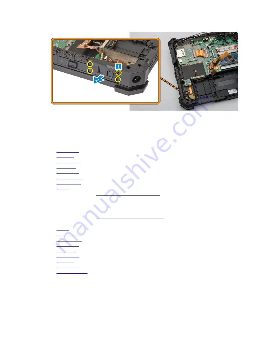
a. Disconnect the LED board from the connector [1,2]
b. Remove the screws from the side of the computer chassis [3].
c. Release the LED board [4].

29

Содержание Latitude 12 Rugged Extreme - 7204

Страница 1: ...Dell Latitude 12 Rugged Extreme 7204 Owner s Manual Regulatory Model P18T Regulatory Type P18T001 ...

Страница 2: ...problem WARNING A WARNING indicates a potential for property damage personal injury or death Copyright 2014 Dell Inc All rights reserved This product is protected by U S and international copyright and intellectual property laws Dell and the Dell logo are trademarks of Dell Inc in the United States and or other jurisdictions All other marks and names mentioned herein may be trademarks of their res...

Страница 3: ...he Hard Drive 12 Installing the Hard Drive 12 Removing the System Fan 12 Installing the System Fan 13 Removing the Memory Module 13 Installing the Memory Module 14 Removing the MEMS Board 14 Installing the MEMS Board 15 Removing the USH Board 15 Installing the USH Board 16 Removing the Docking Board 16 Installing the Docking Board 17 Removing the Heatsink 17 Installing the Heatsink 18 Removing the...

Страница 4: ...the Keyboard Control Board 31 Installing the Keyboard Control Board 32 Removing the Power Connector 33 Installing the Power Connector 34 Removing the Palmrest 34 Installing the Palmrest 35 Removing the Display Assembly 36 Installing the Display Assembly 38 Removing the System Board 38 Installing the System Board 40 3 System Setup 42 Boot Sequence 42 Navigation Keys 42 System Setup Options 43 Updat...

Страница 5: ...ed service technician You should only perform troubleshooting and simple repairs as authorized in your product documentation or as directed by the online or telephone service and support team Damage due to servicing that is not authorized by Dell is not covered by your warranty Read and follow the safety instructions that came with the product CAUTION To avoid electrostatic discharge ground yourse...

Страница 6: ... display 10 Press the power button to ground the system board CAUTION To guard against electrical shock always unplug your computer from the electrical outlet before opening the display CAUTION Before touching anything inside your computer ground yourself by touching an unpainted metal surface such as the metal at the back of the computer While you work periodically touch an unpainted metal surfac...

Страница 7: ...t any external devices such as a port replicator or media base and replace any cards such as an ExpressCard 2 Connect any telephone or network cables to your computer CAUTION To connect a network cable first plug the cable into the network device and then plug it into the computer 3 Replace the battery 4 Connect your computer and all attached devices to their electrical outlets 5 Turn on your comp...

Страница 8: ...inwards 3 Follow the procedures in After Working Inside Your computer Removing the Battery WARNING Using an incompatible battery may increase the risk of fire or explosion Replace the battery only with a compatible battery purchased from Dell The battery is designed to work with your Dell computer Do not use a battery from other computers with your computer WARNING Using an incompatible battery ma...

Страница 9: ... the latch to release the battery c Slide the battery out of the computer Installing the Battery 1 Slide the battery into the battery bay 2 Slide the latch to lock position 3 Follow the procedures in After Working Inside Your computer Removing the Bottom Cover 1 Follow the procedures in Before Working Inside Your Computer 2 Remove battery 3 To remove the bottom cover a Remove the screws that secur...

Страница 10: ...r chassis 3 Install the battery 4 Follow the procedures in After Working Inside Your computer Removing the Keyboard and Keyboard door 1 Follow the procedures in Before Working Inside Your Computer 2 To release the keyboard a Remove the screws that secure the keyboard to the computer chassis 1 b Pry along the edges and flip the keyboard over 2 10 ...

Страница 11: ...board from the computer chassis Installing the Keyboard and Keyboard Door 1 Connect the keyboard cables to its connectors on the keyboard controller card 2 Place the keyboard door over its slot on the computer chassis 3 Tighten the screws that secure the keyboard door to the computer chassis 4 Align the keyboard into its slot on the computer 5 Tighten the screws to secure the keyboard to the compu...

Страница 12: ...ard drive into its place on the computer 2 Close the hard drive bay press latch door 3 Install battery 4 Follow the procedures in After Working Inside Your computer Removing the System Fan 1 Follow the procedures in Before Working Inside Your Computer 2 Remove a battery b bottom cover 3 To remove the system fan a Disconnect the system fan cable from the system board 1 b Remove the screws that secu...

Страница 13: ...stem board connector 4 Install a battery b bottom cover 5 Follow the procedures in After Working Inside Your computer Removing the Memory Module 1 Follow the procedures in Before Working Inside Your Computer 2 Remove a battery b bottom cover 3 To remove the memory module a Pry the securing clips away from the memory module until it pops up b Remove the memory module from its connector on the syste...

Страница 14: ...r Working Inside Your computer Removing the MEMS Board MEMS board is also known as the sensor board 1 Follow the procedures in Before Working Inside Your Computer 2 Remove a battery b bottom cover 3 To remove the MEMS board a Disconnect the cable connected to the MEMS board 1 2 b Remove the screws that secure the MEMS board to the computer chassis 3 c Lift the MEMS board from the computer chassis ...

Страница 15: ...e USH Board 1 Follow the procedures in Before Working Inside Your Computer 2 Remove a battery b bottom cover 3 To remove the USH board a Disconnect the USH board cables from the connectors 1 2 b Remove the screws that secure the board 3 c Lift and flip the board at an angle to access the smart card cable at the bottom 4 d Disconnect the smart card cable and release the USH board from the computer ...

Страница 16: ... battery 6 Follow the procedures in After Working Inside Your computer Removing the Docking Board 1 Follow the procedures in Before Working Inside Your Computer 2 Remove a battery b bottom cover 3 To release the docking board a Disconnect the antenna cables from the docking board 1 CAUTION Exercise caution while disconnecting the antenna cables Improper removal may result in damage breakage of the...

Страница 17: ...ng the Docking Board 1 Connect the docking board connector cable to the system board 2 Flip the docking board and seat it on the slot 3 Tighten the screws to secure the docking board 4 Connect the antenna cables to the docking board 5 Install a bottom cover b battery 6 Follow the procedures in After Working Inside Your Computer Removing the Heatsink 1 Follow the procedures in Before Working Inside...

Страница 18: ...heatsink to its position on the system board 3 Tighten the screws in the numerical sequence depicted on the bracket to secure the heatsink on the system board 4 Install a heatsink b battery 5 Follow the procedures in After Working Inside Your Computer Removing the Speaker 1 Follow the procedures in Before Working Inside Your Computer 2 Remove a battery b bottom cover 3 To remove the speaker a Disc...

Страница 19: ...IM Board Assembly 1 Follow the procedures in Before Working Inside Your Computer 2 Remove a battery b bottom cover 3 To remove the SIM board assembly NOTE SIM board assembly comprises of the SIM board and the SIM bracket a Disconnect the cable from the SIM board 1 2 NOTE You can also disconnect the SIM board cable from the system board but it is not a requirement b Remove the screws that secure th...

Страница 20: ...able to the SIM board connector 5 Connect the cable to the system board if you had disconnected the SIM board cable from the system board 6 Install a bottom cover b battery 7 Follow the procedures in After Working Inside Your Computer Removing the Coin cell Battery 1 Follow the procedures in Before Working Inside Your Computer 2 Remove a battery b bottom cover 3 To remove the coin cell battery a D...

Страница 21: ... the Antenna Routing Bracket 1 Follow the procedures in Before Working Inside Your Computer 2 Remove a battery b bottom cover 3 Remove the tapes that secure the wireless antenna cables 4 To remove the antenna routing bracket a Disconnect all the wireless antenna cables from the connectors 1 b Unroute the antenna cables from the routing channel c Remove the screws that secure the bracket 2 d Lift a...

Страница 22: ...s 5 Secure the tapes to secure the wireless antenna cables 6 Install a bottom cover b battery 7 Follow the procedures in After Working Inside Your Computer Removing the WLAN Card 1 Follow the procedures in Before Working Inside Your Computer 2 Remove a battery b bottom cover c antenna routing bracket 3 Disconnect the antenna cables from the WLAN card 4 To remove the WLAN card a Remove the screw th...

Страница 23: ...5 Follow the procedures in After Working Inside Your Computer Removing the WWAN Card 1 Follow the procedures in Before Working Inside Your Computer 2 Remove a battery b bottom cover c antenna routing bracket 3 To remove the WWAN card a Disconnect the antenna cable from the WWAN card 1 b Remove the screw that secures the WWAN card 2 c Slide the card out of the card connector on the system board and...

Страница 24: ...tom cover c battery 5 Follow the procedures in After Working Inside Your Computer Removing the Global Positioning System GPS Module 1 Follow the procedures in Before Working Inside Your Computer 2 Remove a battery b bottom cover 3 To remove the GPS module a Disconnect the GPS antenna cable from the module 1 b Disconnect the USB cable from the GPS module 2 c Pry the retention latch to release the G...

Страница 25: ... 5 Follow the procedures in After Working Inside Your Computer Removing the Card Bracket 1 Follow the procedures in Before Working Inside Your Computer 2 Remove a battery b bottom cover c docking board d GPS module e USH board f MEMS board g hard drive 3 Unroute the antenna cables by removing the tapes 4 To disconnect the cables a Disconnect the battery cable from the system board and the battery ...

Страница 26: ...nd the C storage cables b Remove the screws that secure the card bracket to the computer chassis 6 To remove the card bracket a Flip the card bracket 1 b Disconnect the camera cable from the connector 2 c Lift up and remove the card bracket 3 26 ...

Страница 27: ... board connector and the system board 8 Install a hard drive b MEMS board c USH board d GPS module e hard drive f bottom cover g battery 9 Follow the procedures in After Working Inside Your Computer Removing the I O Board 1 Follow the procedures in Before Working Inside Your Computer 2 Remove a battery b bottom cover c docking board d GPS module e USH board f MEMS board g hard drive h Disconnect t...

Страница 28: ...dule g docking board h bottom cover i battery 5 Follow the procedures in After Working Inside Your Computer Removing the Fingerprint Reader 1 Follow the procedures in Before Working Inside Your Computer 2 Remove a battery b bottom cover c docking board d GPS module e USH board f MEMS board g hard drive h card bracket 3 To remove the fingerprint reader a Remove the screws that secure the fingerprin...

Страница 29: ...r h battery 4 Follow the procedures in After Working Inside Your computer Removing the LED Board 1 Follow the procedures in Before Working Inside Your Computer 2 Remove a battery b bottom cover c docking board d GPS module e USH board f MEMS board g hard drive h card bracket i fingerprint reader 3 To remove the LED board a Disconnect the LED board from the connector 1 2 b Remove the screws from th...

Страница 30: ...re it 4 Connect the screws to secure the board 5 Connect the LED board to the connector 6 Install a fingerprint reader b card bracket c hard drive d MEMS board e USH board f GPS module g docking board h bottom cover i battery 7 Follow the procedures in After Working Inside Your computer Removing the Battery Board 1 Follow the procedures in Before Working Inside Your Computer 2 Remove a battery b b...

Страница 31: ... Board 1 Slide the battery board to its connector 2 Tighten the screws to secure the battery board 3 Connect the battery cable to the battery board 4 Install a card bracket b hard drive c MEMS board d USH board e GPS module f docking board g bottom cover h battery 5 Follow the procedures in After Working Inside Your computer Removing the Keyboard Control Board 1 Follow the procedures in Before Wor...

Страница 32: ... screws that secure the keyboard control board 1 b Lift the keyboard control board from the computer chassis 2 Installing the Keyboard Control Board 1 Place the keyboard control board in the slot on the computer chassis 2 Tighten the screws to secure the keyboard control board 3 Install a system board b SIM board c battery board d heatsink e WWAN f WLAN g antenna routing bracket h memory i card br...

Страница 33: ...Working Inside Your Computer 2 Remove a battery b bottom cover c docking board d GPS module e USH board f MEMS board g hard drive h Disconnect the battery cable from the battery board i system fan j card bracket k memory module l antenna routing bracket m WLAN n WWAN o heatsink p battery board q SIM board r system board 3 Pull the power connector from slot to release the power connector from the c...

Страница 34: ...the battery cable to the battery board l hard drive m MEMS board n USH board o GPS module p docking board q bottom cover r battery 4 Follow the procedures in After Working Inside Your computer Removing the Palmrest 1 Follow the procedures in Before Working Inside Your Computer 2 Remove a battery b bottom cover c docking board d GPS module e USH board f MEMS board g hard drive h Disconnect the batt...

Страница 35: ...remove the palmrest a Open the display 1 b Pry the palmrest from the retention hooks 2 Installing the Palmrest 1 Align the palmrest and press it firmly 2 Close the display and flip the computer chassis 3 Tighten the screws to secure the palmrest to the computer chassis 4 Install a system board b SIM board c battery board 35 ...

Страница 36: ...he Display Assembly 1 Follow the procedures in Before Working Inside Your Computer 2 Remove a battery b bottom cover c docking board d GPS module e USH board f MEMS board g hard drive h Disconnect the battery cable to from the battery board i card bracket j WLAN k WWAN l heatsink 3 To remove the eDP connector and unroute the display cables a Unroute the display cable from the system board 1 b Remo...

Страница 37: ... b Lift and remove the display hinge cover 2 c Lift and pull the rubber gasket to release the cables routed through the gasket 3 5 Remove the screws that secure the display hinges and flip the computer chassis 6 Unlock the display and lift the display to remove it from the computer chassis 37 ...

Страница 38: ...lace the bracket in its slot 9 Tighten the screws to secure the eDP connector to the system board 10 Route the cable through the routing channels 11 Install a heatsink b WWAN c WLAN d card bracket e Connect the battery cable to battery board f hard drive g MEMS board h USH board i GPS module j docking board k bottom cover l battery 12 Follow the procedures in After Working Inside Your computer Rem...

Страница 39: ...board assembly r keyboard 3 Disconnect the following cables from the system board a I O board cable b speaker cable c coin cell battery cable 4 Disconnect the ribbon cables from the system board 1 2 5 To remove the video connectors a Open the connector latch door b Remove the screws that secure the video connectors 1 c Remove the connectors away from the computer 1 39 ...

Страница 40: ...d to align with the connectors 2 Tighten the screws to secure the system board to the computer chassis 3 Install the eDP connector and place the bracket in its slot 4 Tighten the screws to the secure the eDP connector to the system board 5 Tighten the screws to secure the video connector 6 Close the video connector latch door 7 Flip the computer chassis and connect the ribbon cables to the system ...

Страница 41: ...y c battery board d heatsink e WWAN f WLAN g antenna routing bracket h memory module i card bracket j system fan k hard drive l MEMS board m USH board n GPS module o dock board p bottom cover q battery 10 Follow the procedures in After Working Inside Your computer 41 ...

Страница 42: ...on Self Test POST when the Dell logo appears you can Access System Setup by pressing F2 key Bring up the one time boot menu by pressing F12 key The one time boot menu displays the devices that you can boot from including the diagnostic option The boot menu options are Removable Drive if available STXXXX Drive NOTE XXX denotes the SATA drive number Optical Drive Diagnostics NOTE Choosing Diagnostic...

Страница 43: ...ation Displays BIOS Version Service Tag Asset Tag Ownership Tag Ownership Date Manufacture Date and the Express Service Code Memory Information Displays Memory Installed Memory Available Memory Speed Memory Channels Mode Memory Technology DIMM ASize DIMM B Size Processor Information Displays Processor Type Core Count Processor ID Current Clock Speed Minimum Clock Speed Maximum Clock Speed Processo...

Страница 44: ...Enabled w PXE This option is enabled by default Unmanaged NIC This option controls the on board USB LAN controller This option is enabled by default Parallel Port Allows you to configure the parallel port on the docking station The options are Disabled AT This option is enabled by default PS2 ECP Serial Port 1 Allows you to configure the integrated serial port The options are Disabled COM1 This op...

Страница 45: ...e OS cannot see any device attached to this port Enable USB Boot Support Enable External USB Ports Enable USB3 0 Controller Disable Docking Station Devices except video NOTE USB keyboard and mouse always work in the BIOS setup irrespective of these settings USB PowerShare This option configures the USB PowerShare feature behavior This option is unchecked by default Audio This field enables or disa...

Страница 46: ...tion LCD Brightness Allows you to set the display brightness depending up on the power source On Battery and On AC NOTE The Video setting will only be visible when a video card is installed into the system Table 5 Security Option Description Admin Password Allows you to set change or delete the administrator admin password NOTE You must set the admin password before you set the system or hard driv...

Страница 47: ...s when the admin password is set Default Setting Allow Non Admin Password Changes is selected Non Admin Setup Changes Allows you to determine whether changes to the setup options are allowed when an Administrator Password is set If disabled the setup options are locked by the admin password TPM Security Allows you to enable the Trusted Platform Module TPM during POST Default Setting The option is ...

Страница 48: ...nd dbx appear The options are Save to File Saves the key to a user selected file Replace from File Replaces the current key with a key from a user selected file Append from File Adds a key to the current database from a user selected file Delete Deletes the selected key Reset All Keys Resets to default setting Delete All Keys Deletes all the keys NOTE If you disable the Custom Mode all the changes...

Страница 49: ...fault Setting Disabled Table 8 Power Management Option Description AC Behavior Allows you to enable or disable the computer from turning on automatically when an AC adapter is connected Default Setting Wake on AC is not selected Auto On Time Allows you to set the time at which the computer must turn on automatically The options are Disabled default Every Day Weekdays Select Days USB Wake Support A...

Страница 50: ...es you to maximize the battery health By enabling this option your system uses the standard charging algorithm and other techniques during the non work hours to improve the battery health Disabled default Primary Battery Charge Configuration Allows you to select the charging mode for the battery The options are Adaptive Standard ExpressCharge This option is enabled by default Primarily AC use Cust...

Страница 51: ...yboard Embedded option is not supported in Latitude E5540 Mouse Touchpad Allows you to define how the system handles mouse and touch pad input The options are Serial Mouse PS2 Mouse Toushpad PS 2 Mouse This option is enabled by default Numlock Enable Allows you to enable the Numlock option when the computer boots Enable Network default Fn Key Emulation Allows you to set the option where the Scroll...

Страница 52: ...l Trusted Execution Technology The TPM virtualization Technology and Virtualization technology for direct I O must be enabled to use this feature Trusted Execution disabled by default Table 11 Wireless Option Description Wireless Switch Allows to set the wireless devices that can be controlled by the wireless switch The options are WWAN WLAN WiGig Bluetooth All the options are enabled by default W...

Страница 53: ...om the list 6 Select your computer model and the Product Support page of your computer appears 7 Click Get drivers and click View All Drivers The Drivers and Downloads page opens 8 On the Drivers and Downloads screen under the Operating System drop down list select BIOS 9 Identify the latest BIOS file and click Download File You can also analyze which drivers need an update To do this for your pro...

Страница 54: ...haracters The password can contain the numbers 0 through 9 Only lower case letters are valid upper case letters are not allowed Only the following special characters are allowed space Re enter the system password when prompted 4 Type the system password that you entered earlier and click OK 5 Select Setup Password type your system password and press Enter or Tab A message prompts you to re type th...

Страница 55: ...ter the new password when promoted If you delete the System and or Setup password confirm the deletion when promoted 5 Press Esc and a message prompts you to save the changes 6 Press Y to save the changes and exit from the System Setup The computer reboots 55 ...

Страница 56: ... provide extra information about the failed device s View status messages that inform you if tests are completed successfully View error messages that inform you of problems encountered during testing CAUTION Use the system diagnostics to test only your computer Using this program with other computers may cause invalid results or error messages NOTE Some tests for specific devices require user int...

Страница 57: ...mputer is connected to an electrical outlet the battery light operates as follows Alternately blinking amber light and green light An unauthenticated or unsupported non Dell AC adapter is attached to your laptop Alternately blinking amber light with steady green light Temporary battery failure with AC adapter present Constantly blinking amber light Fatal battery failure with AC adapter present Lig...

Страница 58: ...ed support and service options Availability varies by country and product and some services may not be available in your area To contact Dell for sales technical support or customer service issues 1 Visit dell com support 2 Select your support category 3 Verify your country or region in the Choose a Country Region drop down menu at the top of page 4 Select the appropriate service or support link b...

Отзывы: