


Related Links
Installing the Power Connector
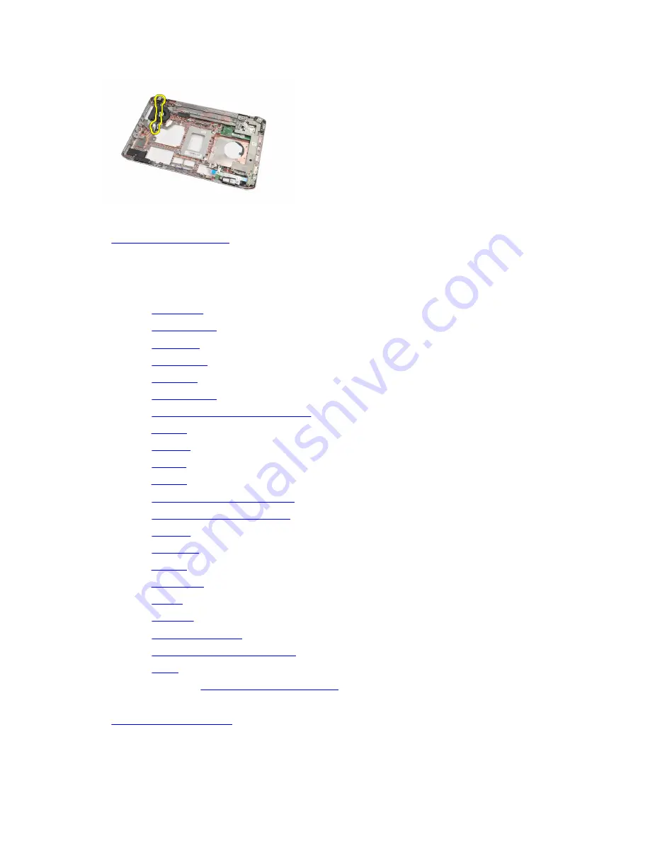
Installing the Power Connector
1.
Secure the power connector to the routing channel on the processor fan.
2.
Replace the
system board
.
3.
Replace the
support brackets
.
4.
Replace the
modem card
.
5.
Replace the
bluetooth card
.
6.
Replace the
audio board
.
7.
Replace the
display assembly
.
8.
Replace the
ExpressCard/Smart Card/PCMCIA module
.
9.
Remove the
palm rest
.
10. Replace the
processor
.
11. Replace the
heat sink
.
12. Remove the
CPU door
.
13. Replace the
wireless wide area network (WWAN)
.
14. Replace the
wireless local area network (WLAN)
.
15. Replace the
hard drive
.
16. Replace the
optical drive
.
17. Remove the
keyboard
.
18. Remove the
keyboard trim
.
19. Replace the
memory
.
20. Replace the
back panel
.
21. Replace the
secure digital (SD) card
.
22. Replace the
subscriber identity module (SIM) card
.
23. Replace the
battery
.
24. Follow the procedures in
After Working Inside Your Computer
.
Related Links
Removing the Power Connector
74
Содержание Inspiron 5520
Страница 1: ...Dell Latitude 5520 E5520 E5520m Owner s Manual Regulatory Model P16G Regulatory Type P16G001 ...
Страница 10: ...10 ...
Страница 12: ...12 ...
Страница 16: ...16 ...
Страница 18: ...18 ...
Страница 20: ...20 ...
Страница 22: ...22 ...
Страница 28: ...28 ...
Страница 38: ...Related Links Removing the Memory Module 38 ...
Страница 40: ...Related Links Removing the CPU Door 40 ...
Страница 42: ...Related Links Removing the Heat Sink 42 ...
Страница 56: ...56 ...
Страница 60: ...60 ...
Страница 70: ...6 Follow the procedures in After Working Inside Your Computer Related Links Removing the Coin Cell Battery 70 ...
Страница 80: ...80 ...
Страница 84: ...84 ...


