background image

3. Lift the fan off the palm-rest and keyboard assembly.

Installing the fan

Prerequisites

Jika Anda mengganti komponen, lepaskan komponen yang ada sebelum melakukan prosedur pemasangan.

About this task

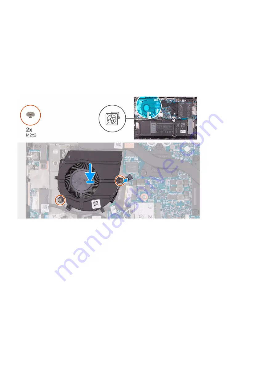
The following image indicates the location of the fan and provides a visual representation of the installation procedure.

Steps

1. Using the alignment posts, place the fan on the palm-rest and keyboard assembly.
2. Replace the two screws (M2x2) that secure the system fan to the palm-rest and keyboard assembly.
3. Connect the fan cable to the system board.

Next steps

1. Install the 

base cover

.

2. Follow the procedure in 

After working inside your computer

.

Board I/O

Removing the I/O board

Prerequisites

1. Follow the procedure in 

Before working inside your computer

.

2. Remove the 

base cover

.

Melepaskan dan memasang komponen

37

Содержание Inspiron 5400 2n1

Страница 1: ...Inspiron 5400 2n1 Service Manual Regulatory Model P126G Regulatory Type P126G002 ...

Страница 2: ...nya data dan memberi tahu Anda mengenai cara menghindari masalah tersebut PERINGATAN PERINGATAN menunjukkan potensi kerusakan harta benda cedera pribadi atau kematian 2020 Dell Inc atau anak anak perusahaannya Seluruh hak cipta dilindungi oleh undang undang Dell EMC dan merek dagang lainnya adalah merek dagang dari Dell Inc atau anak anak perusahaannya Merek dagang lain dapat merupakan merek dagan...

Страница 3: ...ling the battery 17 Baterai sel berbentuk koin 18 Removing the coin cell battery 18 Installing the coin cell battery 19 Modul memori 20 Removing the memory modules 20 Installing the memory modules 21 Speaker 23 Removing the speakers 23 Installing the speakers 23 Unit pendingin 24 Removing the heat sink 24 Installing the heat sink 25 Port adaptor daya 26 Removing the power adapter port 26 Installin...

Страница 4: ...board assembly 51 3 Driver dan Unduhan 53 4 System setup Pengaturan sistem 54 Masuk ke program pengaturan BIOS 54 Tombol navigasi 54 Boot Sequence 54 One time boot menu 55 System setup options 55 Clearing CMOS settings 64 Menghapus kata sandi BIOS Pengaturan Sistem dan Sistem 64 5 Pemecahan Masalah 65 Diagnostik Enhanced Pre Boot System Assessment ePSA 65 Menjalankan Pemeriksaan Kinerja Sistem Pra...

Страница 5: ...k informasi selengkapnya tentang praktik keselamatan terbaik kunjungi home page Kesesuaian Peraturan di www dell com regulatory_compliance CATATAN Lepaskan komputer Anda dari semua sumber daya sebelum membuka penutup komputer atau panel Setelah Anda selesai mengerjakan bagian dalam komputer pasang kembali semua penutup panel dan sekrup sebelum menyambungkan komputer Anda ke stopkontak listrik PERH...

Страница 6: ...enar Penggunaan gelang anti statis nirkabel tidak diizinkan lagi gelang ini tidak memberikan proteksi yang mencukupi Menyentuhkan sasis sebelum menangani bagian tidak menjamin proteksi ESD yang mencukupi pada bagian dengan sensitivitas terhadap kerusakan ESD yang meningkat Tangani semua komponen sensitif statis di area yang aman secara statis Jika memungkinkan gunakan alas lantai dan alas meja ker...

Страница 7: ... rapat dan semua bahan kemasan busa yang sama harus digunakan di kotak asli tempat komponen baru masuk Perangkat sensitif ESD harus dilepaskan dari kemasan hanya di permukaan kerja yang dilindungi ESD dan komponen tidak boleh diletakkan di atas tas ESD karena hanya bagian dalam tas yang terlindungi Selalu letakkan komponen di tangan Anda di alas ESD di sistem atau di dalam tas anti statis Mengangk...

Страница 8: ...sternal periferal atau kabel yang Anda lepaskan sebelum mengerjakan komputer Anda 3 Pasang kembali semua kartu media disk dan komponen lain yang Anda lepaskan sebelum mengerjakan komputer Anda 4 Sambungkan komputer Anda dan semua perangkat yang terpasang ke outlet listrik 5 Hidupkan komputer Anda 8 Bekerja pada bagian dalam komputer Anda ...

Страница 9: ...ti itu saat mengganti komponen CATATAN Warna sekrup dapat berbeda tergantung pada konfigurasi yang dipesan Tabel 1 Screw list Component Secured to Screw type Quantity Screw image Base cover Palm rest and keyboard assembly M2x4 6 Battery Palm rest and keyboard assembly M2x3 5 For computers shipped with 4 cell battery 4 For computers shipped with 3 cell battery Wireless card bracket Wireless card an...

Страница 10: ...onal for configuration with fingerprint reader Palm rest and keyboard assembly M2x3 2 Power adapter port Palm rest and keyboard assembly M2x3 1 USB Type C bracket Palm rest and keyboard assembly M2x3 2 System board Palm rest and keyboard assembly M2x2 2 Major components of Inspiron 5400 2n1 The following image shows the major components of Inspiron 5400 2n1 10 Melepaskan dan memasang komponen ...

Страница 11: ...tate drive thermal bracket NOTE Dell provides a list of components and their part numbers for the original system configuration purchased These parts are available according to warranty coverages purchased by the customer Contact your Dell sales representative for purchase options Penutup bawah Removing the base cover Prerequisites 1 Follow the procedure in Before working inside your computer Abou...

Страница 12: ...12 Melepaskan dan memasang komponen ...

Страница 13: ...Melepaskan dan memasang komponen 13 ...

Страница 14: ...st and keyboard assembly NOTE The following step is applicable only if you want to further remove any other component from your computer 4 Peel the tape that secures the battery cable to the system board 5 Disconnect the battery cable from the system board 6 Turn your computer over and press the power button for 15 seconds to drain the flea power Installing the base cover Prerequisites Jika Anda m...

Страница 15: ...Melepaskan dan memasang komponen 15 ...

Страница 16: ...tong atau menembus baterai dengan benda asing Jangan memaparkan baterai ke suhu tinggi atau membongkar kemasan dan sel baterai Jangan menekan permukaan baterai Jangan menekuk baterai Jangan gunakan alat apa pun untuk mencungkil pada atau melawan baterai Pastikan bahwa selama menyervis produk ini tidak ada sekrup yang hilang atau salah pasang untuk mencegah kebocoran atau kerusakan pada baterai ser...

Страница 17: ...M2x3 that secure the battery to the palm rest and keyboard assembly 4 Lift the battery off the palm rest and keyboard assembly Installing the battery Prerequisites Jika Anda mengganti komponen lepaskan komponen yang ada sebelum melakukan prosedur pemasangan About this task The following image indicates the location of the battery and provides a visual representation of the installation procedure M...

Страница 18: ... computer Baterai sel berbentuk koin Removing the coin cell battery Prerequisites 1 Follow the procedure in Before working inside your computer NOTE Removing the I O board cable is equivalent to removing the coin cell battery It resets the BIOS setup program s settings to default It is recommended that you note the BIOS setup program s settings before removing the coin cell battery 2 Remove the ba...

Страница 19: ...ry off the slot on the palm rest and keyboard assembly Installing the coin cell battery Prerequisites Jika Anda mengganti komponen lepaskan komponen yang ada sebelum melakukan prosedur pemasangan About this task The following image indicates the location of the coin cell battery and provides a visual representation of the installation procedure Melepaskan dan memasang komponen 19 ...

Страница 20: ...the I O board Next steps 1 Install the base cover 2 Follow the procedure in After working inside your computer Modul memori Removing the memory modules Prerequisites 1 Follow the procedure in Before working inside your computer 2 Remove the base cover About this task The following image indicates the location of the memory modules and provides a visual representation of the removal procedure 20 Me...

Страница 21: ...e memory module slot NOTE Repeat step 2 to step 3 to remove any other memory modules installed in your computer Installing the memory modules Prerequisites Jika Anda mengganti komponen lepaskan komponen yang ada sebelum melakukan prosedur pemasangan About this task The following image indicates the location of the memory modules and provides a visual representation of the installation procedure Me...

Страница 22: ...e into the memory module slot 4 Press the memory module down until it clicks into place NOTE If you do not hear the click remove the memory module and reinstall it NOTE Repeat step 2 to step 4 to install any other memory modules in your computer Next steps 1 Install the base cover 2 Follow the procedure in After working inside your computer 22 Melepaskan dan memasang komponen ...

Страница 23: ...board 2 Note the speaker cable routing and remove the speaker cable from the routing guides on the palm rest and keyboard assembly 3 Lift the speakers along with the cables off the palm rest and keyboard assembly Installing the speakers Prerequisites Jika Anda mengganti komponen lepaskan komponen yang ada sebelum melakukan prosedur pemasangan About this task The following image indicates the locat...

Страница 24: ...heat sink Prerequisites 1 Follow the procedure in Before working inside your computer CAUTION For maximum cooling of the processor do not touch the heat transfer areas on the heat sink The oils in your skin can reduce the heat transfer capability of the thermal grease NOTE The heat sink may become hot during normal operation Allow sufficient time for the heat sink to cool before you touch it 2 Rem...

Страница 25: ...en yang ada sebelum melakukan prosedur pemasangan CAUTION Incorrect alignment of the heat sink can damage the system board and processor NOTE If either the system board or the heat sink is replaced use the thermal pad paste provided in the kit to ensure that thermal conductivity is achieved About this task The following image indicates the location of the heat sink and provides a visual representa...

Страница 26: ... steps 1 Install the base cover 2 Follow the procedure in After working inside your computer Port adaptor daya Removing the power adapter port Prerequisites 1 Follow the procedure in Before working inside your computer 2 Remove the base cover About this task The following image indicates the location of the power adapter port and provides a visual representation of the removal procedure 26 Melepas...

Страница 27: ...Remove the screw M2x3 that secures the power adapter port to the palm rest and keyboard assembly 6 Lift the power adapter port along with its cable off the palm rest and keyboard assembly Installing the power adapter port Prerequisites Jika Anda mengganti komponen lepaskan komponen yang ada sebelum melakukan prosedur pemasangan About this task The following image indicates the location of the powe...

Страница 28: ...r port cable to the system board 6 Close the right display hinge 7 Replace the three screws M2 5x5 that secure the right display hinge to the palm rest and keyboard assembly Next steps 1 Install the base cover 2 Follow the procedure in After working inside your computer Panel sentuh Removing the touchpad Prerequisites 1 Follow the procedure in Before working inside your computer 2 Remove the base ...

Страница 29: ...ve the two screws M2x2 that secure the touchpad to the palm rest and keyboard assembly 5 Slide and lift the touchpad off the palm rest and keyboard assembly Installing the touchpad Prerequisites Jika Anda mengganti komponen lepaskan komponen yang ada sebelum melakukan prosedur pemasangan About this task The following image indicates the location of the touchpad and provides a visual representation...

Страница 30: ...the palm rest and keyboard assembly 6 Replace the three screws M2x2 that secure the touchpad bracket to the palm rest and keyboard assembly Next steps 1 Install the battery 2 Install the base cover 3 Follow the procedure in After working inside your computer Solid state drive Removing the M 2 2230 solid state drive Prerequisites 1 Follow the procedure in Before working inside your computer 2 Remov...

Страница 31: ... the solid state drive from the solid state drive slot Installing the M 2 2230 solid state drive Prerequisites Jika Anda mengganti komponen lepaskan komponen yang ada sebelum melakukan prosedur pemasangan About this task This computer supports two solid state drive form factors M 2 2230 M 2 2280 If you are replacing the M 2 2230 solid state drive with an M 2 2280 solid state drive the following im...

Страница 32: ...The following image indicates the location of the M 2 2230 solid state drive and provides a visual representation of the installation procedure 32 Melepaskan dan memasang komponen ...

Страница 33: ... at an angle 7 Replace the screw M2x3 that secures the solid state drive to the solid state drive bracket 8 Align the screw hole on the solid state drive thermal bracket with the screw hole on the palm rest and keyboard assembly 9 Replace the screw M2x3 that secures the solid state drive thermal bracket to the palm rest and keyboard assembly Next steps 1 Install the base cover 2 Follow the procedu...

Страница 34: ... the solid state drive from the solid state drive slot Installing the M 2 2280 solid state drive Prerequisites Jika Anda mengganti komponen lepaskan komponen yang ada sebelum melakukan prosedur pemasangan About this task This computer supports two solid state drive form factors M 2 2230 M 2 2280 If you are replacing the M 2 2280 solid state drive with an M 2 2330 solid state drive the following im...

Страница 35: ...he M 2 2280 solid state drive and provides a visual representation of the installation procedure NOTE Perform step 1 to step 3 if you are replacing the M 2 2230 solid state drive with an M 2 2280 solid state drive Melepaskan dan memasang komponen 35 ...

Страница 36: ...he solid state drive to the solid state drive bracket 8 Align the screw hole on the solid state drive thermal bracket with the screw hole on the palm rest and keyboard assembly 9 Replace the screw M2x3 that secures the solid state drive thermal bracket to the palm rest and keyboard assembly Next steps 1 Install the base cover 2 Follow the procedure in After working inside your computer Kipas Remov...

Страница 37: ...ion procedure Steps 1 Using the alignment posts place the fan on the palm rest and keyboard assembly 2 Replace the two screws M2x2 that secure the system fan to the palm rest and keyboard assembly 3 Connect the fan cable to the system board Next steps 1 Install the base cover 2 Follow the procedure in After working inside your computer Board I O Removing the I O board Prerequisites 1 Follow the pr...

Страница 38: ...m the I O board 5 Open the latch and disconnect the fingerprint reader cable from the I O board 6 Disconnect the coin cell battery cable from the I O board 7 Remove the screw M2x3 that secures the I O board to the palm rest and keyboard assembly 8 Slide and lift the I O board off the palm rest and keyboard assembly Installing the I O board Prerequisites Jika Anda mengganti komponen lepaskan kompon...

Страница 39: ... Connect the fingerprint reader cable to the connector on the I O board and close the latch to secure the cable 7 Connect the coin cell battery cable to the I O board 8 Close the left display hinge 9 Replace the two screws M2 5x5 that secure the left display hinge to the palm rest and keyboard assembly Next steps 1 Install the base cover 2 Follow the procedure in After working inside your computer...

Страница 40: ...e I O board cable from the I O board 5 Open the latch and disconnect the fingerprint reader cable from the I O board 6 Open the latch and disconnect the power button cable from the fingerprint reader board 7 Lift the power button along with its cable off the slot on the palm rest and keyboard assembly Installing the power button board Prerequisites Jika Anda mengganti komponen lepaskan komponen ya...

Страница 41: ...cable to the I O board 6 Align the screw holes on the power button bracket with the screw holes on the palm rest and keyboard assembly 7 Replace the two screws M2x3 that secure power button bracket to the palm rest and keyboard assembly Next steps 1 Install the fan 2 Install the heat sink 3 Install the base cover 4 Follow the procedure in After working inside your computer Unit display Removing th...

Страница 42: ...42 Melepaskan dan memasang komponen ...

Страница 43: ...connect the display cable from the system board 3 Remove the two screws M2 5x5 that secure the left display hinges to the palm rest and keyboard assembly 4 Remove the three screws M2 5x5 that secure the right display hinges to the palm rest and keyboard assembly Melepaskan dan memasang komponen 43 ...

Страница 44: ...splay assembly Prerequisites Jika Anda mengganti komponen lepaskan komponen yang ada sebelum melakukan prosedur pemasangan About this task The following image indicates the location of the display assembly and provides a visual representation of the installation procedure 44 Melepaskan dan memasang komponen ...

Страница 45: ...ssembly 3 Replace the three screws M2 5x5 that secure the right display hinge to the palm rest and keyboard assembly 4 Connect the display cable connector to the system board and close the latch to secure the cable 5 Adhere the tape that secures the display cable to the system board Next steps 1 Install the base cover 2 Follow the procedure in After working inside your computer Melepaskan dan mema...

Страница 46: ...id state drive as applicable 7 Remove the heat sink About this task The following image indicates the connectors on your system board Figure 1 System board connectors 1 Power adapter port cable 2 Display cable 3 Fan cable 4 I O board cable 5 Speaker cable 6 Touchpad cable 7 Keyboard cable 8 USB Type C port bracket The following image indicates the location of the system board and provides a visual...

Страница 47: ...ht display hinge to the palm rest and keyboard assembly 2 Open the hinge at an angle of 90 degrees 3 Peel the tape that secures the USB Type C port bracket to the system board 4 Disconnect the fan cable from the system board Melepaskan dan memasang komponen 47 ...

Страница 48: ... the system board 14 Open the latch and disconnect the display cable from the system board 15 Remove the two screws M2x2 that secures the system board to the palm rest and keyboard assembly 16 Lift the system board off the palm rest and keyboard assembly Installing the system board Prerequisites Jika Anda mengganti komponen lepaskan komponen yang ada sebelum melakukan prosedur pemasangan About thi...

Страница 49: ... two screws M2x2 that secure the system board to the palm rest and keyboard assembly 3 Connect the display cable to the connector on the system board and close the latch to secure the cable 4 Adhere the tape that secures the display cable to the system board Melepaskan dan memasang komponen 49 ...

Страница 50: ...l the M 2 2230 solid state drive or M 2 2280 solid state drive as applicable 4 Install the memory modules 5 Install the coin cell battery 6 Install the battery 7 Install the base cover 8 Follow the procedure in After working inside your computer Unit sandaran tangan dan keyboard Removing the palm rest and keyboard assembly Prerequisites 1 Follow the procedure in Before working inside your computer...

Страница 51: ...st and keyboard assembly Prerequisites Jika Anda mengganti komponen lepaskan komponen yang ada sebelum melakukan prosedur pemasangan About this task The following image indicates the location of the palm rest and keyboard assembly and provides a visual representation of the installation procedure Melepaskan dan memasang komponen 51 ...

Страница 52: ...ll the power adapter port 6 Install the fan 7 Install the heat sink 8 Install the speakers 9 Install the I O board 10 Install the M 2 2230 solid state drive or M 2 2280 solid state drive as applicable 11 Install the memory modules 12 Install the coin cell battery 13 Install the battery 14 Install the base cover 15 Follow the procedure in After working inside your computer 52 Melepaskan dan memasan...

Страница 53: ...r dan Unduhan Saat melakukan pemecahan masalah mengunduh atau memasang driver Anda disarankan untuk membaca artikel Basis Pengetahuan Dell Pertanyaan Umum Driver dan Unduhan SLN128938 3 Driver dan Unduhan 53 ...

Страница 54: ...u nyalakan ulang komputer Anda dan segera tekan F2 Tombol navigasi CATATAN Untuk sebagian besar opsi Pengaturan Sistem perubahan yang Anda buat disimpan tetapi tidak berlaku sampai Anda memulai ulang sistem Tabel 2 Tombol navigasi Tombol Navigasi Panah atas Pindah ke kolom sebelumnya Panah bawah Pindah ke kolom berikutnya Enter Memilih nilai di kolom yang dipilih jika berlaku atau mengikuti tautan...

Страница 55: ...cess the System Setup screen System setup options NOTE Depending on this computer and its installed devices the items that are listed in this section may or may not be displayed Table 3 System setup options System information menu Overview Inspiron 5400 2n1 BIOS Version Displays the BIOS version number Service Tag Displays the Service Tag of the computer Asset Tag Displays the Asset Tag of the com...

Страница 56: ... for the memory DIMM_SLOT1 Displays the memory configuration of DIMM SLOT1 DIMM_SLOT2 Displays the memory configuration of DIMM SLOT2 DEVICES Panel Type Displays the Panel Type of the computer Video Controller Displays the integrate graphics information of the computer Video Memory Displays the video memory information of the computer Wi Fi Device Displays the Wi Fi device installed in the compute...

Страница 57: ...orting Enables or disables Self Monitoring Analysis and Reporting Technology SMART Default OFF Enable Audio Enables or disables all integrated audio controller Default ON Enable Microphone Enables or disables microphone By default Enable Microphone is selected Enable Internal Speaker Enables or disables internal speaker By default Enable Internal Speaker is selected USB Configuration Enables or di...

Страница 58: ...acklight timeout value is only effect when the backlight is enabled Default 10 seconds Table 6 System setup options Video menu Video LCD Brightness Brightness on battery power Sets the screen brightness when the computer is running on battery power Default 50 Brightness on AC power Sets the screen brightness when the computer is running on AC power Default 100 Table 7 System setup options Security...

Страница 59: ...HA 256 Enables or disables the BIOS and the TPM to use the SHA 256 hash algorithm to extend measurements into the TPM PCRs during BIOS boot Default ON Clear Enables or disables the computer to clear the PTT owner information and returns the PTT to the default state Default OFF TPM State Enables or disables the TPM This is the normal operating state for the TPM when you want to use its complete arr...

Страница 60: ...on mode Default Deployed Mode NOTE Deployed Mode should be selected for normal operation of Secure Boot Table 10 System setup options Expert Key Management menu Expert Key Management Enable Custom Mode Enables or disables the keys in the PK KEK db and dbx security key databases to be modified Default OFF Custom Mode Key Management Selects the custom values for expert key management Default PK Tabl...

Страница 61: ... the operating system power option will be blank if it was set to Sleep Battery Charge Configuration Enables the computer to run on battery during power usage hours Use the below options to prevent AC power usage between certain times of each day Default Adaptive Battery settings are adaptively optimized based on your typical battery usage pattern Enable Advanced Battery Charge Configuration Enabl...

Страница 62: ...user input when warnings or errors are detected NOTE Errors deemed critical to the operation of the computer hardware will always halt the computer Enable Adapter Warnings Enables or disables the computer to display adapter warning messages when adapters with too little power capacity are detected Default ON Enable Dock Warning Messages Enables or disables dock warning messages Default ON Fastboot...

Страница 63: ...om Hard Drive Enables the computer to recover from a bad BIOS image as long as the Boot Block portion is intact and functioning Default ON NOTE BIOS recovery is designed to fix the main BIOS block and cannot work if the Boot Block is damaged In addition this feature cannot work in the event of EC corruption ME corruption or a hardware issue The recovery image must exist on an unencrypted partition...

Страница 64: ... than the value specified by the Auto OS Recovery Threshold setup option Default ON Clearing CMOS settings About this task CAUTION Clearing CMOS settings will reset the BIOS settings on your computer Steps 1 Turn off your computer 2 Remove the base cover NOTE The battery must be disconnected from the system board see Step 4 in Removing the base cover 3 Press and hold the power button for 15 second...

Страница 65: ... dilakukan Menjalankan Pemeriksaan Kinerja Sistem Pra Boot SupportAssist langkah 1 Hidupkan komputer Anda 2 Saat komputer booting tekan tombol F12 saat logo Dell muncul 3 Pada layar menu booting pilih opsi Diagnostics Diagnostik 4 Klik anak panah pada pojok kiri bawah Halaman utama diagnostik ditampilkan 5 Tekan anak panah pada pojok kanan bawah untuk masuk ke daftar halaman Item yang terdeteksi a...

Страница 66: ... ROM Read Only Memory 2 3 Tidak ada memori atau RAM Random Access Memory yang terdeteksi 2 4 Kegagalan memori atau RAM Random Access Memory 2 5 Memori yang tidak valid terpasang 2 6 Kesalahan board sistem atau chipset 2 7 Kegagalan display 2 8 Kegagalan rel daya LCD 3 1 Kegagalan baterai CMOS 3 2 Kegagalan PCI kartu chip video 3 3 Gambar pemulihan tidak ditemukan 3 4 Gambar pemulihan ditemukan tet...

Страница 67: ...pada ikon file pembaruan BIOS tersebut lalu ikuti petunjuk yang ditampilkan pada layar Melakukan Flash BIOS Kunci USB langkah 1 Ikuti prosedur dari langkah 1 hingga langkah 7 dalam Mem flash BIOS untuk mengunduh file program pengaturan BIOS terbaru 2 Buat drive USB yang dapat di boot Untuk informasi lebih lanjut lihat artikel basis pengetahuan SLN143196 di www dell com support 3 Salin file program...

Страница 68: ... residual static electricity that remains on the computer even after it has been powered off and the battery has been disconnected from the system board The following procedure provides the instructions on how to release the flea power Steps 1 Turn off your computer 2 Remove the base cover NOTE The battery must be disconnected from the system board See Step 4 in removing the base cover 3 Press and...

Страница 69: ...nomor model lalu klik atau ketuk ikon pencarian untuk melihat artikel terkait Pelajari dan ketahui informasi berikut tentang produk Anda Spesifikasi produk Sistem operasi Menyetel dan menggunakan produk Anda Cadangan data Pemecahan masalah dan diagnosa Pemulihan pabrik dan sistem Informasi BIOS Lihat Saya dan Dell Saya di www dell com support manuals Untuk menemukan Me and My Dell Saya dan Dell Sa...

Отзывы: