Replacing the optical-drive connector board
NOTE:
Before working inside your computer, read the safety information that shipped with your computer and follow
the steps in
Before working inside your computer
. After working inside your computer, follow the instructions in
. For more safety best practices, see the Regulatory Compliance home page at
www.dell.com/regulatory_compliance
Procedure
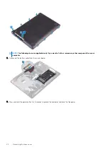
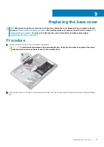
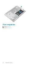
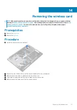
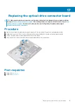
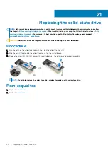
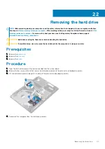
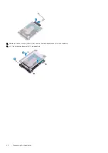
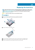
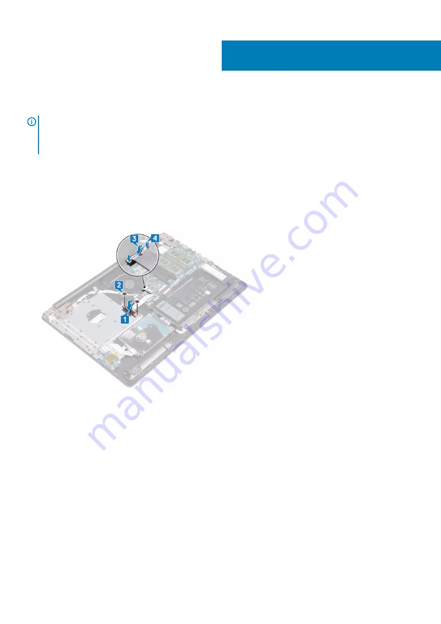
1. Align the screw hole on the optical-drive connector board with the screw hole on the palm rest and keyboard assembly.
2. Replace the two screws (M2x2) that secure the optical-drive connector board to the palm rest and keyboard assembly.
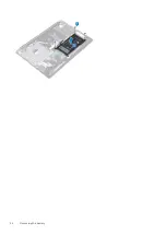
3. Connect the optical-drive connector-board cable to the system board.
4. Close the latch that secures the optical-drive connector-board cable to the system board.
Post-requisites
1. Replace the
.
2. Replace the
17
Replacing the optical-drive connector board
35
Содержание Inspiron 3782
Страница 1: ...Inspiron 3782 Service Manual Regulatory Model P35E Regulatory Type P35E006 ...
Страница 18: ...18 Removing the optical drive ...
Страница 20: ...20 Replacing the optical drive ...
Страница 26: ...26 Removing the battery ...
Страница 28: ...Post requisites 1 Replace the base cover 2 Replace the optical drive 28 Replacing the battery ...
Страница 32: ...32 Removing the wireless card ...
Страница 39: ...Removing the solid state drive 39 ...
Страница 46: ...46 Removing the touchpad ...
Страница 56: ...56 Removing the power adapter port ...
Страница 62: ...62 Removing the display assembly ...
Страница 68: ...68 Removing the power button board ...
Страница 70: ...Post requisites 1 Replace the base cover 2 Replace the optical drive 70 Replacing the power button board ...
Страница 84: ...84 Removing the display panel ...


