


The USB configuration is displayed on the right pane.
4 Check the
Enable External USB Port
check box to either enable or disable it.
5 Save the BIOS setup program settings and exit.
Fixing a no-boot issue caused by USB emulation
Sometimes the computer does not boot to the operating system when USB devices
are connected to the computer during startup. This behavior occurs because the
computer is looking for bootable files in the USB devices. Follow these steps to fix
the no-boot issue:
1
Turn on or restart your computer.
2 Press F2 when the Dell logo is displayed on the screen to enter the BIOS setup
program.
3 On the left pane, select
Settings
>
System Configuration
>
USB
Configuration
.
The USB configuration is displayed on the right pane.
4 Clear the
Enable Boot Support
check box to either enable or disable it.
5 Save the settings and exit.
Wi-Fi
The Inspiron 22–3265 is shipped with the following:
• Wi-Fi 802.11 ac
• Wi-Fi 802.11b/g/n
Turning Wi-Fi on or off
NOTE:
There is no physical switch to enable or disable Wi-Fi. It has to be done
through computer settings.
1
Swipe-in from the right edge of the display, or click or tap the
Action Center
icon on the taskbar to access the Action Center.
2 Click or tap
Wi-Fi
to turn Wi-Fi on or off.
Technology and components
108
Содержание Inspiron 22 3000 SERIES
Страница 1: ...Inspiron 22 3000 Series Service Manual Regulatory Model W17B Regulatory Type W17B001 ...
Страница 25: ...1 stand riser 2 stand base Removing the stand assembly 25 ...
Страница 28: ...1 back cover Removing the back cover 28 ...
Страница 32: ...1 optical drive bezel 2 optical drive 3 optical drive bracket 4 screws 2 Removing the optical drive 32 ...
Страница 36: ...1 screws 3 2 hard drive bracket 3 hard drive Removing the hard drive 36 ...
Страница 39: ...1 system board shield 2 screws 4 3 display assembly base Removing the system board shield 39 ...
Страница 42: ...1 memory module 2 securing clips 2 3 memory module slot Removing the memory module 42 ...
Страница 49: ...3 Replace the stand Replacing the wireless card 49 ...
Страница 54: ...1 microphone cable 2 display assembly base 3 microphone module Removing the microphone 54 ...
Страница 58: ...1 tab 2 camera cable 3 camera frame Removing the camera 58 ...
Страница 61: ...1 coin cell battery 2 battery socket 3 plastic scribe Removing the coin cell battery 61 ...
Страница 64: ...1 fan 2 screws 2 3 display assembly base 4 fan cable 5 system board Removing the fan 64 ...
Страница 67: ...1 screw 2 heat sink 3 captive screws 5 Removing the heat sink 67 ...
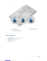
Страница 70: ...1 speaker cable 2 routing guides 3 speakers 2 4 screw 5 tape 6 rubber grommets 4 Removing the speakers 70 ...
Страница 81: ...1 display assembly Removing the display assembly 81 ...
Страница 87: ...12 Replace the optical drive 13 Replace the back cover 14 Replace the stand Replacing the display cable 87 ...
Страница 91: ...12 Replace the back cover 13 Replace the stand Replacing the rubber feet 91 ...
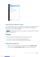
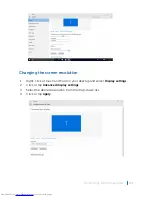
Страница 104: ...2 Click or tap Display 3 Change the display settings as required Technology and components 104 ...


