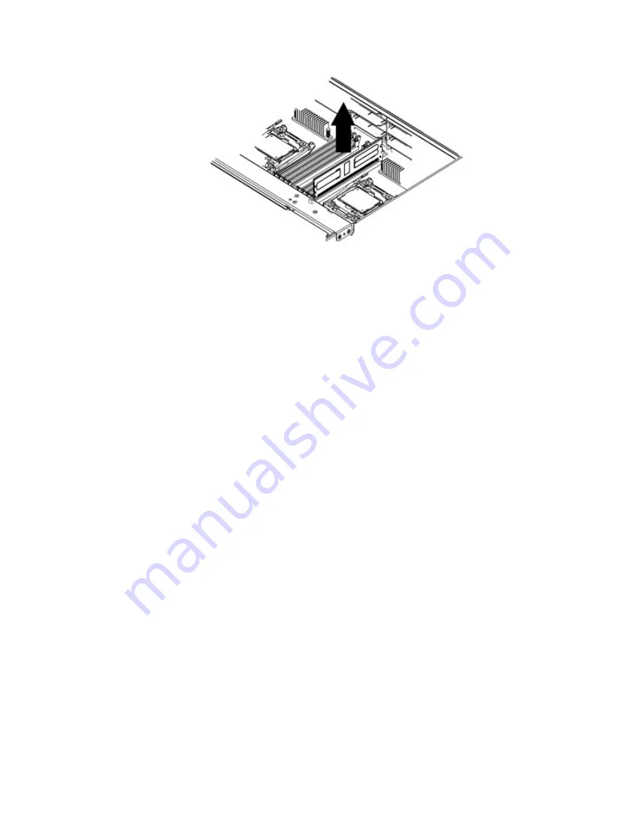
Disassemble SPS assembly
Procedure
1. Remove four screws securing the SLIC cage lever handle to the chassis.
2. Pull up on the SLIC cage lever handle. Pull the SLIC cage forward and remove
the SLIC cage.
3. Remove eight screws from the side of the chassis (four each side) and remove
the fan cage.
4. Disconnect the cable from the rear I/O pcb and pull the rear I/O pcb from its
slot.
5. Disconnect the cable from the SSD pcb and slide the SSD pcb from the 2.5"
HDD bracket.
6. Remove two screws to remove the PDB pcb cover.
7. Remove two screws and remove the PDB pcb.
8. Remove nine screws and remove the DIB pcb.
9. Remove 24 screws and remove the SP pcb from the SP tray.
WEEE Disassembly Instructions
Disassembly instructions
15


