CAUTION:
Do not apply pressure at the center of the memory module; apply pressure at both ends of the
memory module evenly.
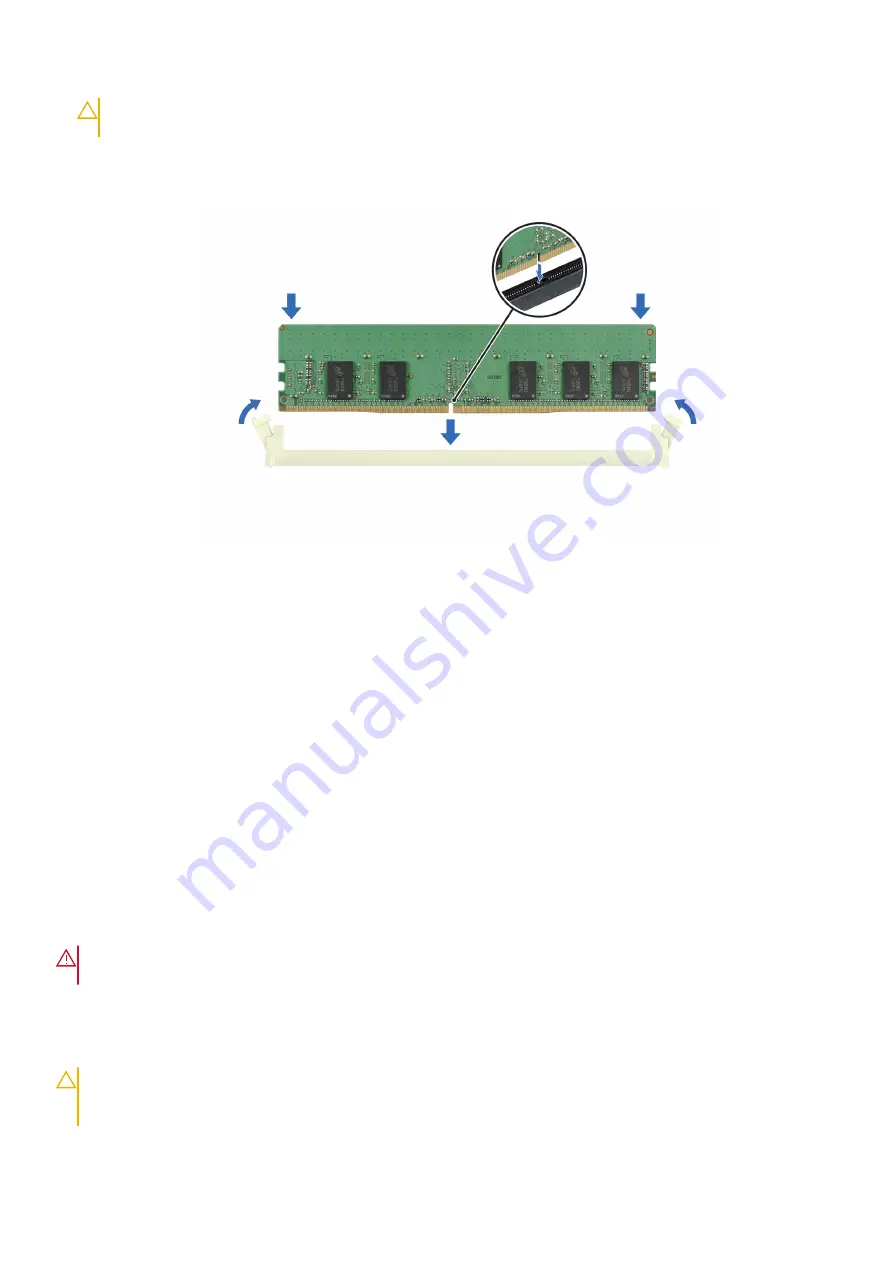
4. Press the memory module with your thumbs until the ejectors firmly click into place. When the memory module is properly
seated in the socket, the levers on the memory module socket align with the levers on the other sockets that have memory
modules installed.
Figure 56. Installing a memory module
Next steps
1.
2. Follow the procedure listed in
After working inside your system
.
3. To verify if the memory module has been installed properly, press F2 and navigate to
System Setup Main Menu > System
BIOS > Memory Settings
. In the
Memory Settings
screen, the System Memory Size must reflect the updated capacity of
the installed memory.
4. If the System Memory Size is incorrect, one or more of the memory modules may not be installed properly. Ensure that the
memory modules are firmly seated in their sockets.
5. Run the system memory test in system diagnostics.
Processor and heat sink module
Removing the processor
Prerequisites
WARNING:
Remove the processor from processor and heat sink module (PHM) only if you are replacing the
processor or heat sink.
1. Follow the safety guidelines listed in the
.
2. Follow the procedure listed in
Before working inside your system
3.
.
4. Remove the processor heat sink module or remove the liquid cooling module
CAUTION:
You may find the CMOS battery loss or CMOS checksum error displayed during the first instance of
powering on the system after the processor or system board replacement which is expected. To fix this, simply
go to setup option to configure the system settings.
64
Installing and removing system components


