background image

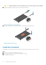
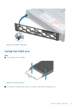
Figure 15. Install the arm

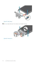
3. Close the arm by connecting it to the bracket on the left side of the chassis.

Figure 16. Close the arm

18

Install the System in the Rack

Содержание EMC PowerProtect DD6400 System

Страница 1: ...Dell EMC PowerProtect DD6400 System Installation and Storage Expansion Guide February 2022 Rev 04 ...

Страница 2: ...tial damage to hardware or loss of data and tells you how to avoid the problem WARNING A WARNING indicates a potential for property damage personal injury or death 2021 2022 Dell Inc or its subsidiaries All rights reserved Dell EMC and other trademarks are trademarks of Dell Inc or its subsidiaries Other trademarks may be trademarks of their respective owners ...

Страница 3: ...emove filler panels 19 Install an ES40 shelf into the rack 19 Installing the rails in the cabinet 19 Installing the shelf on the rails 22 Installing and locking the front bezel 23 Chapter 4 Connect Cables and Power On 25 Connecting ES40 shelves 26 DD6400 with ES40 cabling 26 Connecting data cables 27 Connecting disk shelf power cables 28 Connecting controller power cables and powering on 29 Chapte...

Страница 4: ...alent 40 Chapter 6 Installation Troubleshooting 41 Installation troubleshooting scenarios 41 Appendix A Add Storage Capacity 43 Prepare system for storage expansion 43 Install and connect the new storage 43 Verify and configure the new disks 44 License the new storage with electronic licensing 45 Expand the file system 45 4 Contents ...

Страница 5: ...em into the extended rails 16 12 Slide system into the rack 16 13 Installing the front bezel 17 14 Install the seperator 17 15 Install the arm 18 16 Close the arm 18 17 Holes for alignment pins 21 18 Installing the rails 22 19 Sliding the shelf onto the rails 22 20 Securing the front of the shelf 23 21 Installing the front bezel 24 22 DD6400 with one ES40 shelf 26 23 DD6400 with two ES40 shelves 2...

Страница 6: ...400 to ES40s cabling instructions 26 4 DD6400 with two ES40s ES40 to ES40 cabling instructions 27 5 I O Module Slot assignments 28 6 Maximum FC cable lengths 28 7 iDRAC NIC to physical port mapping 33 8 Communications settings 33 9 Settings page values 39 10 Troubleshooting scenarios 41 Tables 6 Tables ...

Страница 7: ...om the DD OS 7 7 Drivers Downloads section on the Data Domain Product Support page https www dell com support home en us product support product dd os 7 7 drivers For complete instructions on updating your Data Domain OS refer to the Dell EMC Data Domain Software Upgrade in KB 21710 https www dell com support kbdoc 000021710 If you do not take action at this time please be advised that the system ...

Страница 8: ...system Review the following table before installing the DD6400 Requirement Description Rack space DD6400 controller only 2U DD6400 controller with one ES40 5U DD6400 controller with two ES40s 8U Rack power connections Minimum of two redundant PDUs Networking System hostname Minimum of two IP addresses iDRAC static IP address required ethMa List of DNS servers Licenses Electronic license file for t...

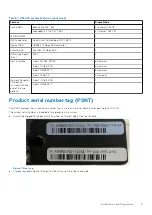
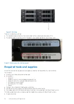
Страница 9: ...bE SFP 3 maximum 4 port 10GBASE T 3 maximum 4 port 16 Gb FC 1 maximum Network Daughter Card option system will have one of the two options 4 port 10 GbE SFP 1 4 port 10GBASE T 1 Product serial number tag PSNT The PSNT provides the system serial number that is used as the initial administrator password for DD OS The system serial number is included in two places on the system A small tag clipped to...

Страница 10: ...Antistatic wrist strap and conductive foam pad Screwdrivers Phillips 1 Phillips 2 with a 4 to 6 inch blade and a magnetic tip Phillips 2 with a 12 in or longer blade and magnetic tip Flat head with a 3 16 in blade Flat head with a 1 4 in blade Torque Flashlight free standing for single person installations Roll of 5 8 inch Velcro cable tie material 3M Scotchmate SJ 3401 or similar Null modem cable...

Страница 11: ...hould not be removed unless a replacement can be added immediately Do not run the system without all parts in place Provide a suitable power source with electrical overload protection Provide a safe electrical ground connection to each power cord Check the grounding of the power sources before applying power A DD6400 system must be operated only from a power supply input voltage range of 100 240 V...

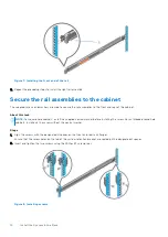
Страница 12: ...em in the cabinet Install the front bezel Install the CMA arm Identifying the rail kit components The 2U sliding rail assemblies allow the server to be secured in the cabinet and extended from the cabinet so that the system cover can be removed to access the internal FRUs Figure 4 Sliding rail assembly 2U systems 1 Sliding rail 2 2 Velcro strap 2 3 Screw 4 4 Washer 4 The rails are compatible with ...

Страница 13: ...et NOTE Install the left rail assembly first 2 Fully extend the rear sliding bracket of the rail 3 Position the rail end piece labeled Left Front facing inward and orient the rear end piece to align with the holes on the rear cabinet flanges 4 Push the rail straight toward the rear of the rack until the latch locks in place Figure 6 Installing the rear end of the rail 5 For the front end piece rot...

Страница 14: ...e hole cabinets install the supplied conical washer before installing the screw For unthreaded round hole cabinets install only the screw without the conical washer Steps 1 Align the screws with the designated U spaces on the front and rear rack flanges Ensure that the screw holes on the tab of the system retention bracket are seated on the designated U spaces 2 Insert and tighten the two screws u...

Страница 15: ...Steps 1 Pull the inner rails out of the rack until they lock into place 2 Release the inner rail lock by pulling forward on the white tabs and sliding the inner rail out of the intermediate rails Figure 9 Pull out the intermediate rail 1 Intermediate rail 2 Inner rail 3 Attach the inner rails to the sides of the system by aligning the J slots on the rail with the standoffs on the system and slidin...

Страница 16: ...ease lock tabs forward on both the rails and slide the system into the rack Figure 12 Slide system into the rack Install the front bezel The procedure to install the front bezel with the LCD panel and the front bezel without the LCD panel is the same Steps 1 Align and insert the right end of the bezel onto the system 2 Press the release button and fit the left end of the bezel onto the system 3 Lo...

Страница 17: ...bezel Install the CMA arm Steps 1 Install the separator on the bracket Figure 14 Install the seperator 2 Install the arm on the right side of the chassis on top of the separator with the open side up Install the System in the Rack 17 ...

Страница 18: ...Figure 15 Install the arm 3 Close the arm by connecting it to the bracket on the left side of the chassis Figure 16 Close the arm 18 Install the System in the Rack ...

Страница 19: ...eps in this section to install the rails ES40 expansion shelf and bezel Follow these steps for each ES40 shelf you are installing There are no specific placement requirements for the ES40 shelves in relation to the DD6400 controller in the rack as long as they are close enough to be connected by cables no longer than five meters NOTE The included cables are one meter Three and five meter cables ar...

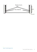
Страница 20: ...Steps 1 From the front of the cabinet insert the rail alignment pins above and below the bottom U mark on the rear cabinet channel 20 Install the Disk Shelves in the Rack ...

Страница 21: ...Alignment pins here EMC2892b 3U Rear channels Figure 17 Holes for alignment pins Install the Disk Shelves in the Rack 21 ...

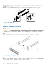
Страница 22: ...the rails About this task CAUTION The system components are heavy To avoid personal injury and or damage to the equipment do not attempt to install or remove system components without a mechanical lift and or help from another person Steps 1 From the front of the cabinet or rack lift the shelf and slide it onto the rails as shown in the following figure CL5845 Figure 19 Sliding the shelf onto the ...

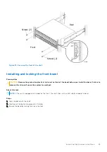
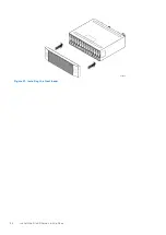
Страница 23: ...zel before you install the bezel Failure to remove this strip will cause the system to overheat About this task NOTE If the rack is equipped with a door on the front the shelf ships with an EMI shield instead of a bezel Steps 1 Align the bezel with the shelf 2 Gently push the bezel into place until it latches 3 Secure the bezel by turning the key in the lock Install the Disk Shelves in the Rack 23...

Страница 24: ...CL5674 Figure 21 Installing the front bezel 24 Install the Disk Shelves in the Rack ...

Страница 25: ...es and Power On Topics Connecting ES40 shelves DD6400 with ES40 cabling Connecting data cables Connecting disk shelf power cables Connecting controller power cables and powering on 4 Connect Cables and Power On 25 ...

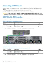
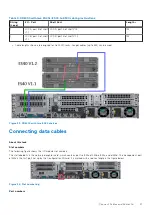
Страница 26: ...ith ES40 cabling The DD6400 system supports a maximum of two ES40 shelves The diagrams show a single shelf and two shelves cabled in a single loop Table 2 DD6400 with one ES40 cabling instructions String Loop I O Port Shelf Port Length a 1 I O 3 Port 0 LCC B port A of the shelf 3M 1 I O 3 Port 1 LCC A port A of the shelf 3M a Cable lengths shown are designed for Dell EMC racks Longer cables up to ...

Страница 27: ...Longer cables up to 5M can be used Figure 23 DD6400 with two ES40 shelves Connecting data cables About this task Slot numbers The following figure shows the I O module slot numbers The slot labeled N is the network daughter card which contains ports ethMa ethMb ethMc and ethMd The management port ethMa is the first port set up by the Configuration Wizard It is marked with a red rectangle in the fi...

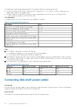
Страница 28: ...Height 4 Broadcom LSI 9300 8e 2 x 12 Gbps SAS PCIe Low Profile internal SAS 6 Steps 1 For 10 GBASE T connections use one of the following Unshielded Cat 6 cables with RJ 45 connectors that do not exceed 55m Cat 6A cables with RJ 45 connectors that do not exceed 100m 2 For 10 GbE SFP optical connections refer to the list of qualified adapters and use an OM1 160 MHz 2 to 26m OM1 200 MHz 2 to 33m OM2...

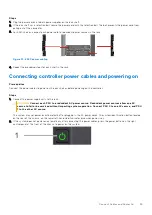
Страница 29: ...owering on the controller Steps 1 Connect the power supply units to the rack CAUTION Connect each PSU to a redundant AC power source Redundant power sources allow one AC source to fail or be serviced without impacting system operation Connect PSU 0 to one AC source and PSU 1 to the other AC source The system may not power on automatically after plugging in the AC power cords The system identificat...

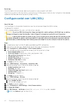
Страница 30: ...BIOS settings as making changes will impact system functionality Contact Support if changes are required in any of these areas The system uses the following key mapping for console redirection Use the ESC 1 key sequence for F1 Use the ESC 2 key sequence for F2 Use the ESC 3 key sequence for F3 Use the ESC 0 key sequence for F10 Use the ESC key sequence for F11 Use the ESC key sequence for F12 Use ...

Страница 31: ...ure 26 iDRAC Settings Network 7 Press Esc to return to the previous menu 8 Select User Configuration a Enable the root user b Change the root user password NOTE The default password is the system serial number The system serial number is always on the service tag at the front of the system and on the PSNT tag attached to the rear handle of the chassis if the system has a rear mounted PSNT tag Figu...

Страница 32: ...wser type the iDRAC IP address specified during iDRAC configuration 2 Login with the user name root The default password is the system serial number on the PSNT 3 Select Configuration BIOS Settings Serial Communications 4 Verify the following values are configured and specify any that are not set as listed Serial Communication Auto Serial Port Address Serial Device1 COM2 Serial Device2 COM1 Extern...

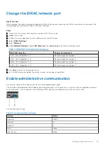
Страница 33: ... 1 1 1 Network daughter card port 1 LOM2 NIC Integrated 1 2 1 Network daughter card port 2 LOM3 NIC Integrated 1 3 1 Network daughter card port 3 LOM4 NIC Integrated 1 4 1 Network daughter card port 4 7 Press Esc to return to the previous menu 8 Exit the BIOS menu and reboot the system to allow the change to take effect Enable administrative communication For HA pairs administrative communication ...

Страница 34: ...console 1 Log in to the system console using the sysadmin username localhost localdomain login sysadmin 2 Type the default password which is the system serial number The system serial number is a 14 character alphanumeric string starting with APM The sticker with the serial number on it is located on the front of the system Password system_serial_number NOTE If you type an incorrect password four ...

Страница 35: ...licts with the DDOS iDRAC interconnect do not configure 169 254 0 X and 169 254 1 X IP addresses Steps 1 Enter yes to configure the system for network connectivity Network Configuration Configure Network at this time yes no no yes 2 Enter yes to configure DHCP Dynamic Host Configuration Protocol to obtain network parameters such as the host name domain name and IP addresses dynamically from a DHCP...

Страница 36: ... one two or three IP addresses 192 168 10 1 9 A summary of the network settings is displayed You can accept the settings Save reject the settings and exit to the CLI Cancel or return to the beginning of the current section and change the settings Retry Entering Retry displays your previous responses for each prompt Press Return to accept the displayed value or enter a new one Pending Network Setti...

Страница 37: ... Lab 5000 Apple Drive Suite 130 Dallas Tx 3 To add one or more time servers enter ntp add timeserver 192 168 101 1 Remote Time Servers 192 168 10 1 4 To enable the NTP daemon enter ntp enable NTP enabled 5 To change the system time zone enter NOTE This requires a system reboot config set timezone US Central The Timezone name is US Central You made a change to the timezone setting To fully effect t...

Страница 38: ... dialog box to select which features to configure and to advance through the wizard To display help for a feature click the help icon question mark in the lower left corner of the dialog box License The License section enables you add modify or delete licenses from a license file DDOS supports licensing via the Electronic License Management System ELMS which enables you to include multiple feature...

Страница 39: ...Virtual Edition VE Gateway provides automated connect home and remote support activities through an IP based solution that is enhanced by a comprehensive security system About this task An on site Secure Remote Services version 3 gateway provides the ability to monitor both on site protection systems and DDVE instances and cloud based DDVE instances Steps 1 Select Maintenance Support Autosupport 2...

Страница 40: ...air as a user will fail and cause the RSA key token to become out of synch 3 To enable the sending of autosupports enter support notification enable all Enabled sending autosupport and alerts to EMC 4 To set the notification method to ConnectEMC enter support notification method set connectemc Support notification method set to connectemc 5 To show the notification setup enter support notification...

Страница 41: ...HBA DDOS does not load Reinstall DDOS The DDOS USB Installation Guide provides instructions to reinstall DDOS from a USB image Incorrect version of DDOS installed Upgrade to the desired DDOS version CAUTION Fresh installing a lower version of DDOS is not supported iDRAC is not working Verify iDRAC connectivity Verify there are no conflicts with the iDRAC IP address Verify iDRAC is set to use a sta...

Страница 42: ...SFPs are fully seated and are known to be functional ES40 shelves not detected Verify the SAS HBA and all SAS cables are fully seated NVRAM not charged The NVRAM module takes 2 3 hours to reach 80 charge If the NVRAM is not charged to 80 or more the system will generate errors and performance is degraded License file is missing or incomplete Contact your Dell EMC sales representative Open a licens...

Страница 43: ...n before proceeding with the upgrade procedure Steps 1 Log in as a sysadmin user 2 Display the current alerts on the system Run the following command alerts show current alerts show current No active alerts 3 Resolve all displayed alerts 4 Run the filesys disable command to disable the file system Install and connect the new storage Verify a license exists for the new capacity before attempting to...

Страница 44: ...w enclosure All the new disks should display in the Unknown state For a new ES40 disk show state Enclosure Disk 1 2 3 4 5 6 7 8 9 10 11 12 13 14 15 16 1 2 3 U U U U U U U U U U U U U U U Legend State Count In Use Disks 27 U Unknown Disks 15 Total 42 disks 5 Run the storage add enclosure enclosure number command to add the new enclosure to the Data Domain system volume The command prompts for confi...

Страница 45: ...lectronic license file txt Run the command without parameters to run the command interactively elicense update Enter the content of license file and then press Control D or press Control C to cancel Expand the file system Prerequisites The new storage must be added to the file system before it can be used About this task Complete the following tasks to add the new storage to the file system Steps ...

Страница 46: ...otal 42 disks For a new ES40 disk show state Enclosure Disk 1 2 3 4 5 6 7 8 9 10 11 12 13 14 15 16 1 2 3 Legend State Count In Use Disks 42 Total 42 disks 4 Display the current alerts on the system Run the following command alerts show current alerts show current No active alerts 5 Resolve all displayed alerts 46 Add Storage Capacity ...

Отзывы: