background image


50 

Dell EMC Networking with Isilon Front-End Deployment and Best Practices Guide | version 1.0 

S4048-ON Leaf 1  

S4048-ON Leaf 2  

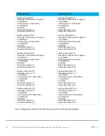
interface port-channel49 
 description 

“Spine 1” 

 no shutdown 
 switchport mode trunk 
 switchport trunk allowed vlan 100 
 mtu 9216 
 vlt-port-channel 49 
 
interface ethernet1/1/49 
 description 

“Spine 1” 

 no shutdown 
 no switchport 
 channel-group 49 mode active 
 mtu 9216 
 
interface ethernet1/1/50 
 description 

“Spine 2” 

 no shutdown 
 no switchport 
 channel-group 49 mode active 
 mtu 9216 


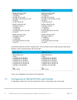
Uplink Failure Detection (UFD) is configured next.  UFD is a feature that shuts down specified downstream 
interfaces when all specified uplinks become disabled. 

S4048-ON Leaf 1  

S4048-ON Leaf 2  

uplink-state-group 1 
 enable 
 downstream port-channel1 
 downstream port-channel3 
 downstream port-channel5 
 downstream port-channel101 
 downstream port-channel102 
 upstream port-channel49 
 
end 
write memory 

uplink-state-group 1 
 enable 
 downstream port-channel1 
 downstream port-channel3 
 downstream port-channel5 
 downstream port-channel101 
 downstream port-channel102 
 upstream port-channel49 
 
end  
write memory 


Finally, exit configuration mode and save the configuration. 

7.3 

Configuration of S4048-ON OS9 Leaf Switches 

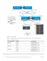
Configurations in this section cover the leaf switches 3 and 4 running OS9 as seen in Figure 24. 

Содержание EMC PowerEdge R640

Страница 1: ...Dell EMC Networking with Isilon Front End Deployment and Best Practices Guide Dell EMC Networking Infrastructure Solutions June 2018 ...

Страница 2: ...disclaims implied warranties of merchantability or fitness for a particular purpose Use copying and distribution of any software described in this publication requires an applicable software license Copyright 2018 Dell Inc or its subsidiaries All Rights Reserved Dell EMC and other trademarks are trademarks of Dell Inc or its subsidiaries Other trademarks may be the property of their respective own...

Страница 3: ... Scaling 13 4 4 Layer 3 leaf spine topology 14 4 5 Layer 2 leaf spine topology 15 5 Layer 3 Topology preparation 16 5 1 BGP ASN configuration 16 5 2 Loopback addresses 16 5 3 Point to point interfaces 17 6 Configuration of Layer 3 Topology 19 6 1 Configuration of Z9100 ON OS10EE Spine Switches 19 6 2 Configuration of S4048 ON OS10EE Leaf Switches 23 6 3 Configuration of S4048 ON OS9 Leaf Switches ...

Страница 4: ...luster 67 9 2 Configuring LACP to each node 69 9 3 Configuring SMB share 72 9 4 Setting up DNS for SmartConnect 73 9 5 Validation 74 A Validated hardware and components 76 A 1 Dell EMC Networking Switches 76 A 2 Dell EMC Isilon Array 76 A 3 Dell EMC PowerEdge Servers 76 B Product Manuals and technical guides 77 C Support and feedback 78 ...

Страница 5: ...tection replication load balancing storage tiering and cloud integration Isilon solutions remain simple to manage no matter how large the data environment becomes All nodes work together as peers in the cluster leaving no single point of failure As nodes are added OneFS expands dynamically and redistributes data eliminating the work of partitioning disks and creating volumes Additionally OneFS ens...

Страница 6: ...dware that is available The first example will highlight the benefits of using the dynamic routing protocol Border Gateway Protocol BGP in a leaf spine environment This will be followed up with an example that displays the configuration and benefits of a layer 2 leaf spine topology While the steps in this document were validated using the specified Dell EMC Networking switches and operating system...

Страница 7: ...nospace Text CLI examples that wrap the page This text is entered as a single command Italic Monospace Text Variables in CLI examples Bold Monospace Text Commands entered at the CLI prompt Bold text GUI fields and information entered in the GUI 1 2 Attachments This pdf includes switch configuration file attachments To access attachments in Adobe Acrobat Reader click the icon in the left pane halfw...

Страница 8: ... S4048 ON The S4048 ON is a 1RU switch with forty eight 10GbE SFP ports and six ports of 40GbE In this guide this switch is deployed as a leaf switch performing basic gateway functionality for attached Windows servers and Isilon nodes Dell EMC Networking S4048 ON 2 3 Dell EMC Networking Z9100 ON The Dell EMC Networking Z9100 ON is a 1RU multilayer switch with thirty two ports supporting 10 25 40 5...

Страница 9: ...0 server is a 2 socket 1 RU server This server is used in the second rack to connect to the Isilon storage Dell EMC PowerEdge R640 2 6 Isilon X210 The Dell EMC Isilon X210 is a 2 RU scale out NAS system The Isilon X210 is used to create a storage cluster to support an SMB share in this guide Dell EMC Isilon X210 front view Dell EMC Isilon X210 rear view ...

Страница 10: ...management connections Each switch has a connection from the out of band OOB management port to the ToR as well as each Isilon Node and PowerEdge server The first Isilon node management connections are shown each additional node is cabled similarly This can be seen in Figure 9 below all equipment in other racks is configured in a similar fashion Management configurations for rack 1 ...

Страница 11: ...ied by the number of spine switches The bandwidth of the fabric may be increased by adding connections between the leaf and spine layer as long as the spine layer has the capacity for the additional connections Leaf Spine architecture 4 1 Design considerations There are many different options regarding the selection of the correct topology that will best fit the needs of the data center In this se...

Страница 12: ...Trunking VLT Dell EMC recommends that RSTP always is configured as a best practice Although configuring VLT will create a loop free topology RSTP will prevent loops if there is a misconfiguration in the network 4 2 Oversubscription Oversubscription is equal to the total amount of bandwidth available to all servers connected to a leaf switch divided by the amount of uplink bandwidth In a leaf spine...

Страница 13: ...ine switches Server Storage interfaces Server connections to leaf switches Leaf connections to spine switches per rack Total connections for leaf switches to four spine switches Connections 4 19 x 4 76 4 per leaf switch 2 leaf switches per rack 8 links 16 racks 8 128 Speed of Ports 10 GbE 10 GbE 40 GbE 40 GbE Total theoretical available bandwidth 4 x 10 40GbE 76 x10 760GbE 8 40GbE per rack 320GbE ...

Страница 14: ... and spines is routed The layer 2 3 boundary is at the leaf switches Spine switches are never connected to each other in a layer 3 topology Equal cost multi path routing ECMP is used to load balance traffic across the layer 3 network Connections within racks from hosts to leaf switches are layer 2 Connections to external networks are made from a pair of edge or border leafs as shown in Figure 12 L...

Страница 15: ...ween leafs and spines is switched except for a pair of edge leafs as shown in Figure 13 VLT is used for multipathing and load balancing traffic across the layer 2 leaf spine fabric Connections from hosts to leaf switches are also layer 2 For connections to external networks layer 3 links are added between the spines and a pair of edge leafs Layer 2 leaf spine network ...

Страница 16: ...GP ASN assignments ASNs should follow a logical pattern for ease of administration and allow for growth as additional leaf and spine switches are added In this example an ASN with a 6 in the hundreds place represents a spine switch e g 64601 and an ASN with a 7 in the hundreds place represents a leaf switch e g 64701 Note The same ASN can be used across all tier 2 spine switches if the growth plan...

Страница 17: ...yer 3 connection details for each leaf and spine switch All addresses come from the same base IP prefix 192 168 0 0 16 with the third octet representing the spine number For example 192 168 1 0 31 is a two host subnet connected to Spine 1 while 192 168 2 0 31 is connected to Spine 2 This IP scheme is easily extended as leaf and spine switches are added to the network Link labels are provided in th...

Страница 18: ... 1 49 5 192 168 1 4 31 Spine 1 Eth1 1 3 4 F Leaf 3 Eth1 1 50 5 192 168 2 4 31 Spine 2 Eth1 1 3 4 G Leaf 4 Eth1 1 49 7 192 168 1 6 31 Spine 1 Eth1 1 4 6 H Leaf 4 Eth1 1 50 7 192 168 2 6 31 Spine 2 Eth1 1 4 6 The point to point IP addresses used in this guide are shown in Figure 16 Point to point IP addresses ...

Страница 19: ...gram Each subsequent node is cabled similarly The configurations for all connections are detailed in the following sections The Isilon nodes will all connect on the back end network through two InfiniBand switches creating one single six node cluster The Isilon back end networking is not covered in this guide Layer 3 Topology Note The configuration files for every switch in this topology are liste...

Страница 20: ...igure terminal hostname Z9100 Spine2 interface mgmt 1 1 1 no ip address dhcp no shutdown ip address 100 67 169 36 24 management route 0 0 0 0 0 100 67 169 254 Configure the four point to point interfaces connected to leaf switches In this example each of the connections from the Z9100 ON spine to the S4048 ON leaf switches needs to have the speed set to 40GbE Next assign IP addresses per Table 3 C...

Страница 21: ...s 10 0 1 1 32 interface breakout 1 1 1 map 40g 1x interface breakout 1 1 2 map 40g 1x interface breakout 1 1 3 map 40g 1x interface breakout 1 1 4 map 40g 1x interface ethernet1 1 1 1 description S4048 Leaf1 no shutdown no switchport mtu 9216 ip address 192 168 2 0 31 interface ethernet1 1 2 1 description S4048 Leaf2 no shutdown no switchport mtu 9216 ip address 192 168 2 2 31 interface ethernet1 ...

Страница 22: ...outing table In this topology there are two equal cost best paths from a spine to a host one to each leaf that the host is connected BGP neighbors are configured and Neighbor fall over is enabled Graceful restart enables the data plane to continue forwarding traffic for a time if the BGP process fails or quits BGP hello and hold down timers are set to three and nine seconds respectively Neighbor f...

Страница 23: ...or 192 168 1 7 inherit template spine leaf remote as 64704 no shutdown end write memory router bgp 64602 bestpath as path multipath relax graceful restart role receiver only maximum paths ebgp 2 address family ipv4 unicast redistribute connected route map spine leaf template spine leaf advertisement interval 1 fall over timers 3 9 neighbor 192 168 2 1 inherit template spine leaf remote as 64701 no...

Страница 24: ...OS10EE Leaf pair The interfaces for additional Isilon nodes and servers in this example can be found in the following table Interface enumeration Server Isilon Node Switch Leaf interface Node 01 1 Leaf 1 ethernet 1 1 1 Leaf 2 ethernet 1 1 1 Node 01 2 Leaf 1 ethernet 1 1 3 Leaf 2 ethernet 1 1 3 ...

Страница 25: ...48 Leaf1 interface mgmt 1 1 1 no ip address dhcp ip address 100 67 170 15 24 management route 0 0 0 0 0 100 67 170 254 no iscsi enable spanning tree mode rstp spanning tree rstp priority 0 configure terminal hostname S4048 Leaf2 interface mgmt 1 1 1 no ip address dhcp ip address 100 67 170 14 24 management route 0 0 0 0 0 100 67 171 254 no iscsi enable spanning tree mode rstp spanning tree rstp pr...

Страница 26: ...to give predictability of VRRP master The higher priority will be elected as the master If no priority is given the higher IP address will be elected as the master S4048 ON Leaf 1 S4048 ON Leaf 2 interface vlan 100 ip address 172 16 1 252 24 no shutdown mtu 9216 vrrp group 100 priority 150 virtual address 172 16 1 254 interface vlan 100 ip address 172 16 1 253 24 no shutdown mtu 9216 vrrp group 10...

Страница 27: ...access vlan 100 mtu 9216 vlt port channel 1 spanning tree port type edge interface port channel3 description Isilon Node 2 no shutdown switchport access vlan 100 mtu 9216 vlt port channel 3 spanning tree port type edge interface port channel5 description Isilon Node 3 no shutdown switchport access vlan 100 mtu 9216 vlt port channel 5 spanning tree port type edge interface port channel101 descripti...

Страница 28: ...itchport mtu 9216 flowcontrol receive on flowcontrol transmit off interface ethernet1 1 1 description Isilon Node 1 10gige 2 no shutdown channel group 1 mode active no switchport mtu 9216 flowcontrol receive on flowcontrol transmit off interface ethernet1 1 3 description Isilon Node 2 10gige 2 no shutdown channel group 3 mode active no switchport mtu 9216 flowcontrol receive on flowcontrol transmi...

Страница 29: ...esses and leaf networks via BGP The command ip prefix list spine leaf seq 10 permit 10 0 2 0 24 ge 32 includes all addresses in the 10 0 2 0 24 address range with a mask greater than or equal to 32 This includes all loopback addresses used as router IDs The command ip prefix list spine leaf seq 20 permit 172 16 0 0 16 ge 24 includes the 172 16 2 0 24 network used on Leaf switches 3 and 4 as shown ...

Страница 30: ...es the maximum number of parallel paths to a destination to add to the routing table In this topology there are two equal cost best paths from a spine to a host one to each leaf that the host is connected BGP neighbors are configured and Neighbor fall over is enabled Graceful restart enables the data plane to continue forwarding traffic for a time if the BGP process fails or quits BGP hello and ho...

Страница 31: ...r 192 168 1 0 inherit template spine leaf remote as 64601 no shutdown neighbor 192 168 2 0 inherit template spine leaf remote as 64602 no shutdown end write memory router bgp 64702 bestpath as path multipath relax graceful restart role receiver only maximum paths ebgp 2 address family ipv4 unicast redistribute connected route map spine leaf template spine leaf advertisement interval 1 fall over ti...

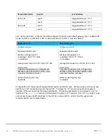
Страница 32: ...onfigurations in this section cover leaf switches 3 and 4 running OS9 as seen in Figure 20 OS9 Leaf pair The ports for additional Isilon nodes and servers in this example can be found in the following table Interface enumeration Server Isilon Node Switch Leaf interface Node 01 4 Leaf 3 tengigabitethernet 1 1 1 Leaf 4 tengigabitethernet 1 1 1 ...

Страница 33: ...af 4 configure terminal hostname S4048 Leaf3 interface management 1 1 ip address 100 67 171 15 24 no shutdown management route 0 0 0 0 0 100 67 171 254 protocol lldp advertise management tlv management address system description system name advertise interface port desc protocol spanning tree rstp bridge priority 0 no disable configure terminal hostname S4048 Leaf4 interface management 1 1 ip addr...

Страница 34: ...yGigE 1 53 channel member fortyGigE 1 54 no shutdown no switchport interface fortyGigE 1 53 description VLTi no shutdown no switchport interface fortyGigE 1 54 description VLTi no shutdown no switchport vlt domain 127 peer link port channel 128 back up destination 100 67 171 15 unit id 1 peer routing The downstream interfaces will be configured in the next section Dell recommends asymmetrical flow...

Страница 35: ... off interface tengigabitethernet 1 19 description Server 4 1 no shutdown port channel protocol LACP port channel 102 mode active mtu 9216 flowcontrol rx on tx off interface tengigabitethernet 1 1 description Isilon Node 4 10gige 2 no shutdown port channel protocol LACP port channel 1 mode active mtu 9216 flowcontrol rx on tx off interface tengigabitethernet 1 3 description Isilon Node 5 10gige 2 ...

Страница 36: ...tion would be as follows for that example interface tengigabitethernet 1 1 description Isilon Node 4 10gige 1 switchport no shutdown mtu 9216 interface vlan200 no shutdown mtu 9216 ip address 172 16 2 252 24 untagged port channel 3 5 101 102 untagged interface te 1 1 Configure the necessary port channels There will be one port channel for each server as well as a single port channel for each of th...

Страница 37: ...annel3 description Isilon Node 5 no shutdown switchport mtu 9216 vlt peer lag port channel 3 spanning tree rstp edge port interface port channel5 description Isilon Node 6 no shutdown switchport mtu 9216 vlt peer lag port channel 5 spanning tree rstp edge port interface port channel101 description Server 3 no shutdown switchport mtu 9216 vlt peer lag port channel 101 spanning tree rstp edge port i...

Страница 38: ...port mtu 9216 ip address 192 168 1 5 31 interface fortyGigE 1 50 description Spine 2 no shutdown no switchport mtu 9216 ip address 192 168 2 5 31 interface loopback0 description Router ID no shutdown ip address 10 0 2 3 32 interface fortyGigE 1 49 description Spine 1 no shutdown no switchport mtu 9216 ip address 192 168 1 7 31 interface fortyGigE 1 50 description Spine 2 no shutdown no switchport ...

Страница 39: ...ce fortyGigE 1 50 link bundle monitor enable ecmp group 1 interface fortyGigE 1 49 interface fortyGigE 1 50 link bundle monitor enable Uplink Failure Detection UFD is configured next UFD shuts down all downstream interfaces if all uplinks fail S4048 ON Leaf 3 S4048 ON Leaf 4 uplink state group 1 downstream port channel1 downstream port channel3 downstream port channel5 downstream port channel101 d...

Страница 40: ...hbor 192 168 1 4 remote as 64601 neighbor 192 168 1 4 peer group spine leaf neighbor 192 168 1 4 no shutdown neighbor 192 168 2 4 remote as 64602 neighbor 192 168 2 4 peer group spine leaf neighbor 192 168 2 4 no shutdown end write memory router bgp 64704 bgp bestpath as path multipath relax bgp graceful restart bgp graceful restart role receiver only maximum paths ebgp 2 redistribute connected ro...

Страница 41: ... The two spine switches will be configured in a VLT The benefits and draw backs of a L2 configuration were referenced in Chapter 4 1 The Isilon nodes will all connect to each switch in the leaf pair using an LACP port channel for each node the connections for the Windows servers will be similarly configured Also each Isilon Node will be connected on the back end network through two InfiniBand swit...

Страница 42: ...hes Z9100 ON Spine 1 Z9100 ON Spine 2 configure terminal hostname Z9100 Spine1 interface mgmt 1 1 1 no ip address dhcp no shutdown ip address 100 67 169 37 24 management route 0 0 0 0 0 100 67 169 254 spanning tree mode rstp spanning tree rstp priority 0 configure terminal hostname Z9100 Spine2 interface mgmt 1 1 1 no ip address dhcp no shutdown ip address 100 67 169 36 24 management route 0 0 0 0...

Страница 43: ...216 ip address 172 16 1 252 24 vrrp group 100 priority 150 virtual address 172 16 1 254 interface vlan200 no shutdown mtu 9216 ip address 172 16 2 252 24 vrrp group 200 priority 150 virtual address 172 16 2 254 interface vlan100 no shutdown mtu 9216 ip address 172 16 1 253 24 vrrp group 100 priority 100 virtual address 172 16 1 254 interface vlan200 no shutdown mtu 9216 ip address 172 16 2 253 24 ...

Страница 44: ...annel group 50 mode active mtu 9216 interface ethernet1 1 4 1 description R2 Leaf B no shutdown no switchport channel group 50 mode active mtu 9216 end write memory interface breakout 1 1 3 map 40g 1x interface breakout 1 1 4 map 40g 1x interface port channel49 description R1 Leaf AandB no shutdown switchport mode trunk switchport trunk allowed vlan 100 mtu 9216 vlt port channel 49 interface port ...

Страница 45: ...t and Best Practices Guide version 1 0 Finally exit configuration mode and save the configuration 7 2 Configuration of S4048 ON OS10EE Leaf Switches Configurations of Leaf 1 and Leaf 2 running OS10EE will be shown next as seen in Figure 23 OS10EE Leaf pair ...

Страница 46: ...ue for RSTP The no iscsi enable command is issued to ensure that iSCSI snooping is disabled S4048 ON Leaf 1 S4048 ON Leaf 2 configure terminal hostname S4048 Leaf1 interface mgmt 1 1 1 no ip address dhcp ip address 100 67 170 15 24 management route 0 0 0 0 0 100 67 170 254 no iscsi enable configure terminal hostname S4048 Leaf2 interface mgmt 1 1 1 no ip address dhcp ip address 100 67 170 14 24 ma...

Страница 47: ... 127 backup destination 100 67 170 15 discovery interface ethernet 1 1 53 1 1 54 Next we will create the VLANs IP addresses and VRRP is configured at the spine layer On each leaf switch the respective VLAN will be defined without an IP address or VRRP S4048 ON Leaf 1 S4048 ON Leaf 2 interface vlan100 no shutdown interface vlan100 no shutdown Configure the downstream port channels There will be one...

Страница 48: ...access vlan 100 mtu 9216 vlt port channel 1 spanning tree port type edge interface port channel3 description Isilon Node 2 no shutdown switchport access vlan 100 mtu 9216 vlt port channel 3 spanning tree port type edge interface port channel5 description Isilon Node 3 no shutdown switchport access vlan 100 mtu 9216 vlt port channel 5 spanning tree port type edge interface port channel101 descripti...

Страница 49: ...erver 2 1 no shutdown channel group 102 mode active no switchport mtu 9216 flowcontrol receive on flowcontrol transmit off interface ethernet1 1 1 description Isilon Node 1 10gige 2 no shutdown channel group 1 mode active no switchport mtu 9216 flowcontrol receive on flowcontrol transmit off interface ethernet1 1 3 description Isilon Node 2 10gige 2 no shutdown channel group 3 mode active no switc...

Страница 50: ...mode active mtu 9216 interface ethernet1 1 50 description Spine 2 no shutdown no switchport channel group 49 mode active mtu 9216 Uplink Failure Detection UFD is configured next UFD is a feature that shuts down specified downstream interfaces when all specified uplinks become disabled S4048 ON Leaf 1 S4048 ON Leaf 2 uplink state group 1 enable downstream port channel1 downstream port channel3 down...

Страница 51: ...nd servers in this example can be found in the following table Interface enumeration Server Isilon Node Switch Leaf interface Node 01 4 Leaf 3 tengigabitethernet 1 1 1 Leaf 4 tengigabitethernet 1 1 1 Node 01 5 Leaf 3 tengigabitethernet 1 1 3 Leaf 4 tengigabitethernet 1 1 3 Node 01 6 Leaf 3 tengigabitethernet 1 1 5 Leaf 4 tengigabitethernet 1 1 5 ...

Страница 52: ...ion system name advertise interface port desc protocol spanning tree rstp no disable configure terminal hostname S4048 Leaf4 interface management 1 1 ip address 100 67 171 15 24 no shutdown management route 0 0 0 0 0 100 67 171 254 protocol lldp advertise management tlv management address system description system name advertise interface port desc protocol spanning tree rstp no disable Configure ...

Страница 53: ...n no switchport interface fortyGigE 1 53 description VLTi no shutdown no switchport interface fortyGigE 1 54 description VLTi no shutdown no switchport vlt domain 127 peer link port channel 128 back up destination 100 67 171 15 unit id 1 Note When port channel 128 is added to the vlt domain the MTU setting is automatically changed to 9216 The downstream interfaces will be configured in the next se...

Страница 54: ... 1 description Isilon Node 4 10gige 2 no shutdown port channel protocol LACP port channel 1 mode active mtu 9216 flowcontrol rx on tx off interface tengigabitethernet 1 3 description Isilon Node 5 10gige 2 no shutdown port channel protocol LACP port channel 3 mode active mtu 9216 flowcontrol rx on tx off interface tengigabitethernet 1 5 description Isilon Node 6 10gige 2 no shutdown port channel p...

Страница 55: ...nning tree rstp edge port interface port channel102 description Server 4 no shutdown switchport mtu 9216 vlt peer lag port channel 102 spanning tree rstp edge port interface port channel1 description Isilon Node 4 no shutdown switchport mtu 9216 vlt peer lag port channel 1 spanning tree rstp edge port interface port channel3 description Isilon Node 5 no shutdown switchport mtu 9216 vlt peer lag po...

Страница 56: ...50 description Spine 1 and 2 no shutdown switchport mtu 9216 vlt peer lag port channel 50 interface fo 1 49 description Spine 1 no shutdown port channel protocol LACP port channel 50 mode active mtu 9216 interface fo 1 50 description Spine 2 no shutdown port channel protocol LACP port channel 50 mode active mtu 9216 Next we will create the VLANs There will be one VLAN for each Isilon subnet this w...

Страница 57: ...nstream port channel5 downstream port channel101 downstream port channel102 upstream port channel 50 end write memory uplink state group 1 downstream port channel1 downstream port channel3 downstream port channel5 downstream port channel101 downstream port channel102 upstream port channel 50 end write memory Finally exit configuration mode and save the configuration with the end and write commands...

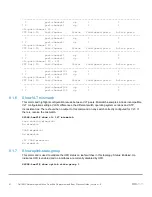
Страница 58: ...and one leaf Command output on other switches is similar 8 1 1 show ip bgp summary When BGP is configured this command shows the status of all BGP connections Each spine has four neighbors the four leafs and each leaf has two neighbors the two spines Z9100 Spine1 show ip bgp summary BGP router identifier 10 0 1 1 local AS number 64601 Neighbor AS MsgRcvd MsgSent Up Down State Pfx 192 168 1 1 64701...

Страница 59: ... 1 3 via 192 168 1 5 via 192 168 1 7 B EX 10 0 2 1 32 via 192 168 1 1 20 0 00 55 44 B EX 10 0 2 2 32 via 192 168 1 3 20 0 00 54 54 B EX 10 0 2 3 32 via 192 168 1 5 20 0 01 38 06 B EX 10 0 2 4 32 via 192 168 1 7 20 0 01 37 52 B EX 172 16 1 0 24 via 192 168 1 1 20 0 00 54 54 via 192 168 1 3 B EX 172 16 2 0 24 via 192 168 1 5 20 0 01 37 49 via 192 168 1 7 S4048 Leaf1 show ip route bgp Codes C connect...

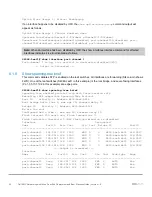
Страница 60: ... 6a e6 b6 14 VLT MAC address f4 8e 38 20 44 29 IP address fda5 74c8 b79e 1 2 Delay Restore timer 90 seconds Peer Routing Enabled Peer Routing Timeout timer 0 seconds VLTi Link Status port channel1000 up VLT Peer Unit ID System MAC Address Status IP Address Version 1 f4 8e 38 20 44 29 up fda5 74c8 b79e 1 1 1 0 8 1 4 Show VLT backup link This command is used to verify that the back up destination is...

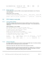
Страница 61: ...gured ports Active ports 1 port channel102 up 1 1 2 port channel102 up 1 1 8 1 6 Show VLT mismatch This command highlights configuration issues between VLT peers Mismatch examples include incompatible VLT configuration settings VLAN differences the different switch operating system versions and STP inconsistencies There should be no output to this command on any switch correctly configured for VLT...

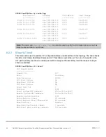
Страница 62: ...e and sever facing interfaces Po 1 3 5 101 102 in this example are edge ports S4048 Leaf1 show spanning tree brief Spanning tree enabled protocol rstp with force version rstp Executing IEEE compatible Spanning Tree Protocol Root ID Priority 0 Address 6400 6ae6 b614 Root Bridge hello time 2 max age 20 forward delay 15 Bridge ID Priority 0 Address 6400 6ae6 b614 We are the root Configured hello time...

Страница 63: ...er 64703 BGP local RIB Routes to be Added 0 Replaced 0 Withdrawn 0 16 network entrie s using 1216 bytes of memory 30 paths using 3240 bytes of memory BGP RIB over all using 3270 bytes of memory 19 BGP path attribute entrie s using 3456 bytes of memory 17 BGP AS PATH entrie s using 170 bytes of memory 2 neighbor s using 16384 bytes of memory Neighbor AS MsgRcvd MsgSent TblVer InQ OutQ Up Down State...

Страница 64: ...t connections 8 2 3 Show VLT brief This command is used to validate VLT configuration status on leaf switches in this topology The Inter chassis link ICL Link Status Heart Beat Status and VLT Peer Status must all be up The role of one switch in the VLT pair is primary not shown and its peer switch is assigned the secondary role Ensure peer routing is shown as enabled S4048 Leaf3 show vlt brief VLT...

Страница 65: ...h S4048 Leaf3 show vlt mismatch S4048 Leaf3 8 2 6 Show uplink state group This command is used to validate the UFD status on leaf switches in this topology Status Enabled Up indicates UFD is enabled and no interfaces are currently disabled by UFD S4048 Leaf3 show uplink state group 1 Uplink State Group 1 Status Enabled Up If an interface happens to be disabled by UFD the show uplink state group co...

Страница 66: ...7 128 6 Po 101 128 102 128 1800 FWD vlt 0 0 f48e 382e a0f7 128 102 Po 102 128 103 128 1800 FWD vlt 0 0 f48e 382e a0f7 128 103 Po 128 128 129 128 600 FWD vltI 0 0 f48e 382e a0f7 128 129 Interface Name Role PortID Prio Cost Sts Cost Link type Edge Po 1 Desg 128 2 128 1800 FWD 0 vlt P2P Yes Po 3 Desg 128 4 128 1800 FWD 0 vlt P2P Yes Po 5 Desq 128 6 128 1800 FWD 0 vlt P2P Yes Po 101 Desg 128 102 128 1...

Страница 67: ...t were used in this example If any additional information is needed on the setup and configuration of the Isilon Array cluster refer to the Isilon X210 Installation Guide Initial configuration wizard The following table outlines the configurations that were made in this example The following configurations will be made in this section The cluster name is defined IP ranges are assigned for the back...

Страница 68: ...lt Commit changes Yes Note Additional information and configuration for SmartConnect will be provided in Section 9 5 When the first node is configured and the cluster has been created the other nodes can then be added into the cluster All nodes will be able to discover the cluster over the back end network The assorted options for back end networking and Isilon are not covered in this document for...

Страница 69: ...the OneFS web GUI This section will cover the creation of two subnets and their associated IP pools as well as the addition of static routes to ensure end to end connectivity This will include ensuring that the LACP option is selected and the appropriate interfaces are selected 1 Navigate to a web page and use the first IP address in the range defined for the ext 1 interface https 100 67 170 140 8...

Страница 70: ...s 172 16 1 254 MTU 9000 Jumbo Frame SmartConnect Service IP 172 16 1 249 SmartConnect Service Name sczone1 dell local Subnet Name subnet2 Netmask 255 255 255 0 Gateway Address 172 16 2 254 MTU 9000 Jumbo Frame SmartConnect Service IP 172 16 2 249 SmartConnect Service Name sczone2 dell local 4 Select the More option next to subnet1 and Add pool 5 Define the pool name pool1 6 Set the IP range 172 16...

Страница 71: ... OneFS This is necessary to enable traffic to cross between the two subnets 1 Navigate Network configurations subnet1 pool1 Add static route to subnet 2 Parameter Value Subnet 172 16 2 0 Netmask 255 255 255 0 Gateway 172 16 1 254 2 Navigate Network configurations subnet2 pool2 Add static route to subnet 1 Parameter Value Subnet 172 16 1 0 Netmask 255 255 255 0 Gateway 172 16 2 254 ...

Страница 72: ...Create a New NIC Team on a Host Computer or VM 9 3 Configuring SMB share This section will cover the creation of a folder structure that will then be configured under OneFS Protocols Windows Sharing SMB Once the folders are added to the Windows Sharing SMB section and the network is properly configured the folder will be accessible via a Windows server 1 From the OneFS GUI select File System File ...

Страница 73: ...0 All other selections were left at the default values 11 Click Create Share 9 4 Setting up DNS for SmartConnect One of the features of the OneFS file system is SmartConnect SmartConnect allows the workload to be dynamically reassigned to other nodes in the cluster in the event of a node failure SmartConnect is a feature that must be configured There is also a DNS dependency for SmartConnect to fu...

Страница 74: ... dell local 172 16 2 249 It is important that the DNS Host A record have a unique name that does not match the name that was assigned to the SmartConnect zone within the OneFS file system The Delegation zone however needs to have a name that matches the SmartConnect zone This will ensure that a connection to sczone1 dell local will reference the SmartConnect Zone 1 IP of 172 16 1 249 When this IP ...

Страница 75: ... the OneFS file system 2 Create a file or a folder in order to verify read write permissions 3 Login to Server04 and issue the Run command sczone1 dell local This will display the same folder and the previously created files will be present In addition to accessing the files on the opposite subnet a test should be done to ensure that each server can access the files through the local subnet Exampl...

Страница 76: ...ersion 2 Z9100 ON OS 10 4 0 R3 2 S4048 ON OS 10 4 0 R3 2 S4048 ON OS 9 13 0 0 1 S3048 ON OS 9 13 0 0 A 2 Dell EMC Isilon Array Qty Item OS Firmware version 6 Isilon X210 8 1 0 1 A 3 Dell EMC PowerEdge Servers Qty Item OS Firmware version 2 R730xd OS Windows Server 2016 BIOS 2 5 5 iDRAC 2 50 50 50 Mellanox ConnectX 4 LX 25GbE SFP adapter 14 20 18 20 Inter Ethernet 10G X520 18 3 6 Intel Ethernet 10G...

Страница 77: ...ation for Dell Networking S4048 ON Manuals and documentation for Dell Networking S3048 ON Manuals and documentation for PowerEdge R730xd Manuals and documentation for PowerEdge R640 Isilon OneFS Isilon X210 Installation Guide Create a New NIC Team on a Host Computer or VM Microsoft s DNS Resource Record Management Dell EMC Leaf Spine Deployment Guide Dell EMC Networking L3 Design for Leaf Spine wi...

Страница 78: ...t and feedback Contacting Technical Support Support Contact Information Web http support dell com Telephone USA 1 800 945 3355 Feedback for this document We encourage readers to provide feedback on the quality and usefulness of this publication by sending an email to Dell_Networking_Solutions Dell com ...

Отзывы: