9. Lift the system board from the three plastic standoffs that secure the system board to the chassis.
10. Carefully lift the system board out from the I/O gasket (see
), and remove the board from the computer.
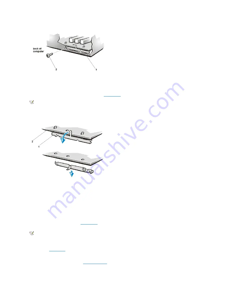
11. Remove the mounting bracket from the back of the system board as shown in the following figure.
Before you install a replacement system board, perform the following steps:
1. Install the guide bracket assembly for the SECC2 package. (The assembly is keyed for correct insertion.)
2. Install the SECC2 package and heat sink assembly.
3. Transfer the DIMMs to the new system board.
When you install a replacement system board, angle the back of the board downward and carefully align the connectors on the back edge of the
board with the cutouts in the I/O gasket (see
). When properly aligned, the board connectors slide into the I/O gasket as you lower
the board into position in the chassis and reseat it on the three plastic standoffs. Replace the system-board mounting screw.
After you install the replacement system board, replace the expansion cards that you removed from the old system board.
When you reconnect the cables to a system board with integrated sound, connect the CD-ROM drive audio cable to the connector nearest the
back edge of the
. The middle audio connector may be used with a modem.
To configure the system after you install a replacement board, perform the following steps:
1. Install the jumper plug on pins 2 and 3 of
J8A1 to select Maintenance mode.
2. Replace the cover and support beam, and boot the system.
1
System board-mounting bracket
2
Mounting screw
NOTE: You may need to slide the board toward the front of the computer to clear the hooked standoffs before you can lift the board from
the computer.
1
System board-mounting bracket
2
System board
NOTE: The system-board mounting screw pulls the board against the I/O gasket to prevent electromagnetic interference (EMI) leakage.
Содержание Dimension XPS T R Series
Страница 45: ...Back to Contents Page ...


