


Installing DC Power Entry Modules
|
35
8
Installing DC Power Entry Modules
The C7004/C150 has six power supply slots at the front-bottom of the chassis (
). The slots
accept either AC power supplies (PSUs) or DC Power Entry Modules (PEMs). Dell Networking does not
support the use of a combination of AC and DC.
•
If you select DC, the C7004/C150 requires at least one DC PEM for operation, but Dell Networking
recommends a one-plus-one redundancy configuration. Those DC PEMs are inserted in slots 0 and 2.
•
To protect against high-voltage shock, install a power supply blank on all unused power supply slots.
NOTE:
The C7004/C150 DC Power Entry Module does not support PoE or PoE+ line cards.
NOTE:
Some C7004/C150 chassis may require Dell Networking assistance when using some DC power
supplies. Please contact the Dell Networking TAC if you experience any difficulty during installation.
Recommended Normal Operating Conditions
Redundancy
For full facility redundancy, install two DC PEMs. Each PEM must be attached to an independent power
source with a dedicated circuit breaker sized in accordance with your local building and electrical safety
codes.
Cable and Connector Requirements
You must provide your own cables to connect to a remote power source (a circuit breaker panel, for
example) in your equipment rack or facility. Cables must be sized to meet the following criteria:
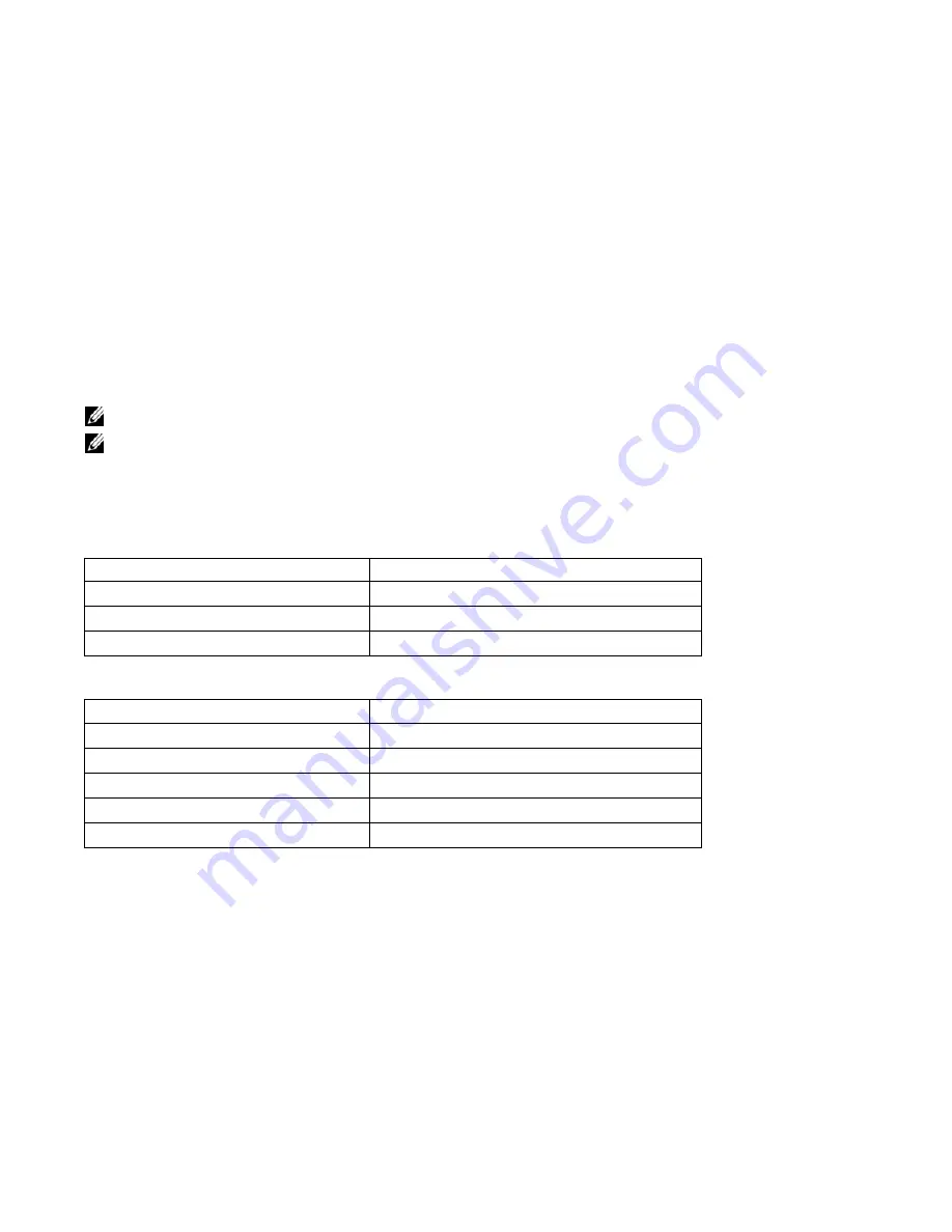
Table 8-1. Input voltage
Input Ranges
Maximum Power
-44V (minimum)
1408 watts
-48V (typical)
1536 watts
-55V (maximum)
1760 watts
Table 8-2. Operating Ranges
Ambient Temperature
Operating Range
-5° C to +40° C
Storage Range
-40° C to +70 ° C
Humidity
Operating Range
5-85% RH
Storage Range
5-90% RH
Содержание C7004/C150
Страница 1: ...Installing and Maintaining the C7004 C150 System ...
Страница 6: ...6 Contents w w w d e l l c o m s u p p o r t d e l l c o m ...
Страница 14: ...14 Preparing the Site w w w d e l l c o m s u p p o r t d e l l c o m ...
Страница 18: ...18 Installing the C7004 C150 Chassis w w w d e l l c o m s u p p o r t d e l l c o m ...
Страница 28: ...28 Management Cable Pinout w w w d e l l c o m s u p p o r t d e l l c o m ...
Страница 40: ...40 Installing DC Power Entry Modules w w w d e l l c o m s u p p o r t d e l l c o m ...
Страница 44: ...44 Powering Up w w w d e l l c o m s u p p o r t d e l l c o m ...
Страница 61: ...System Specifications 61 Figure B 2 Chassis Dimensions Depth 15 5 inches ...
Страница 70: ...70 Contacting Technical Support w w w d e l l c o m s u p p o r t d e l l c o m ...
Страница 71: ......
Страница 72: ...w w w d ell com support dell com Printed in the U S A ...


