background image

13


Installation

|

Unpacking the Cabinet

CAUTION:


Unpacking the cabinet in a low-temperature environment may cause condensation to occur in and

on the cabinet. Do not install the cabinet until the inside and outside of the cabinet are absolutely dry (hazard
of electric shock).

CAUTION:


The cabinet is heavy (see page 63). Use caution to unpack and move the cabinet.

Use care when moving and opening the carton. Leave the components packaged until ready to install.

To unpack the system:

1

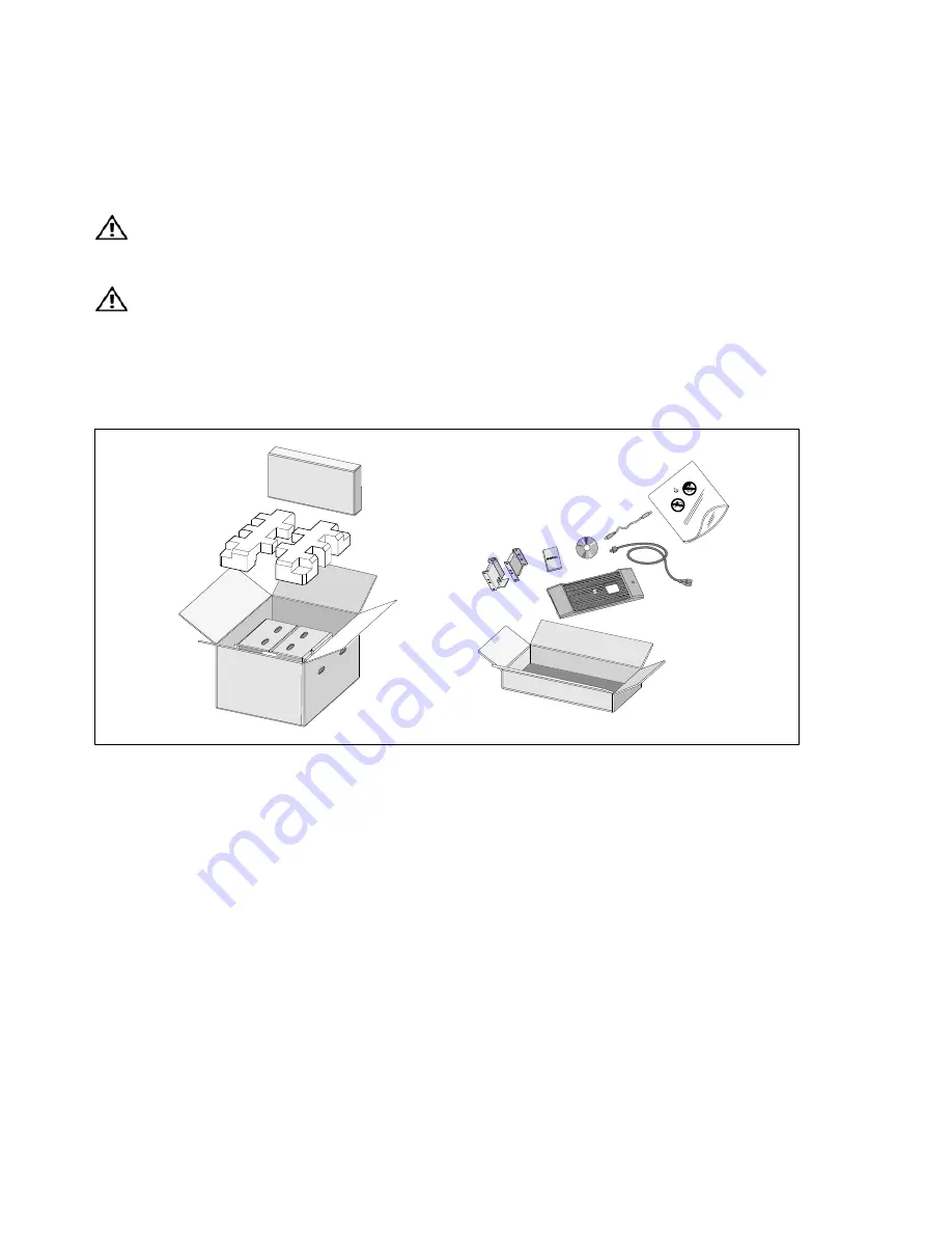
Open the outer carton and remove the accessories packaged with the cabinet (see Figure 2).

Figure 2. Unpacking the Cabinet

Содержание 2700W

Страница 1: ...Dellt Online Rack UPS 2700W User s Guide K803N H950N J728N H967N w w w d e l l c o m s u p p o r t d e l l c o m ...

Страница 2: ...ontains LETHAL VOLTAGES All repairs and service should be performed by AUTHORIZED SERVICE PERSONNEL ONLY There are NO USER SERVICEABLE PARTS inside the UPS Information in this document is subject to change without notice E 2009 Dell Inc All rights reserved Reproduction in any manner whatsoever without the written permission of Dell Inc is strictly forbidden Trademarks used in this text Dell and th...

Страница 3: ... 13 Identifying the UPS Rear Panels 15 Identifying the UPS Front Panel 16 Rackmount Setup 17 Installing the EBM 24 Installing the UPS 26 Installing Remote Emergency Power off 27 UPS Initial Startup 29 4 Operation UPS Startup and Shutdown 31 Starting the UPS 31 Starting the UPS on Battery 32 UPS Shutdown 32 Control Panel Functions 33 Changing the Language 34 ...

Страница 4: ...etrieving the Event Log 48 Behavior on Overload 48 Configuring Load Segments 49 Controlling Load Segments Through the Display 49 Configuring Automatic Start Delay 50 Configuring Automatic on Battery Shutdown 51 Configuring Battery Settings 52 Configuring the UPS for an EBM 52 Running Automatic Battery Tests 53 Configuring Automatic Battery Tests 53 Configuring Automatic Restart 53 5 Additional UPS...

Страница 5: ...UPS 58 Storing the UPS and Batteries 61 When to Replace Batteries 61 Testing Batteries 62 Updating the UPS Firmware 62 7 Specifications 8 Troubleshooting Accessing Alarms and Conditions 66 UPS Status Menu 66 Event Log Menu 67 Typical Alarms and Conditions 67 Silencing the Alarm 71 ...

Страница 6: ...oblems have the potential to corrupt critical data destroy unsaved work sessions and damage hardware causing hours of lost productivity and expensive repairs With the Dell Online Rack UPS you can safely eliminate the effects of power disturbances and guard the integrity of your equipment The UPS s flexibility to handle an array of network devices makes it the perfect choice to protect your LANs se...

Страница 7: ...not available S Maintenance is simplified by allowing the safe replacement of batteries without powering down the UPS S Extended runtime with an optional External Battery Module EBM for 2700W UPS models S Emergency shutdown control through the Remote Emergency Power off REPO ports S Two standard communication ports USB and DB 9 serial port S Optional Dell Network Management Card with enhanced comm...

Страница 8: ... S Specifications S How to configure UPS settings S How to troubleshoot and solve problems S How to install REPO control Dell UPS User s Guide The user s guide is available on the Dell UPS disc and on support dell com S Safety instructions S Regulatory information S Recycling information Safety Environmental and Regulatory Information S Warranty information S Terms and Conditions U S only S End Us...

Страница 9: ...y S This UPS contains its own energy source batteries The output receptacles may carry live voltage even when the UPS is not connected to an AC supply S Do not remove or unplug the input cord when the UPS is turned on This removes the safety ground from the UPS and the equipment connected to the UPS S To reduce the risk of fire connect only to a circuit provided with branch circuit overcurrent pro...

Страница 10: ... equipment and remote battery supplies not having a grounded supply circuit S ELECTRIC ENERGY HAZARD Do not attempt to alter any battery wiring or connectors Attempting to alter wiring can cause injury S Replace batteries with the same number and type of batteries as originally installed in the UPS S Proper disposal of batteries is required Refer to your local codes for disposal requirements S Nev...

Страница 11: ...11 Safety Warnings WARNING Slide rail mounted equipment is not to be used as a shelf or work space Do not add weight to slide rail mounted equipment ...

Страница 12: ...nd packing materials for the carrier or place of purchase and file a claim for shipping damage If you discover damage after acceptance file a claim for concealed damage To file a claim for shipping damage or concealed damage 1 File with the carrier within 15 days of receipt of the equipment 2 Send a copy of the damage claim within 15 days to your service representative NOTE Check the battery recha...

Страница 13: ...ide and outside of the cabinet are absolutely dry hazard of electric shock CAUTION The cabinet is heavy see page 63 Use caution to unpack and move the cabinet Use care when moving and opening the carton Leave the components packaged until ready to install To unpack the system 1 Open the outer carton and remove the accessories packaged with the cabinet see Figure 2 Figure 2 Unpacking the Cabinet ...

Страница 14: ...he handles on the cardboard and set it on a flat stable surface see Figure 3 Place the cabinet in a protected area that has adequate airflow and is free of humidity flammable gas and corrosion Figure 3 Lifting the Cabinet 3 Discard or recycle the packaging in a responsible manner or store it for future use ...

Страница 15: ...s Load Segment 1 REPO Ports RS 232 Port Ground Screw Two IEC 320 C13 Receptacles Load Segment 2 EBM Connector Cover Strain Relief Bracket Figure 4 2700W 120V Rear Panel IEC C20 Input Connector UPS Communication Bay USB Port REPO Ports RS 232 Port One L6 20 Receptacle Load Segment 1 EBM Connector Cover Strain Relief Bracket Two L6 30 Receptacles Load Segment 2 Ground Screw Figure 5 2700W 208V Rear ...

Страница 16: ...Segment 2 EBM Connector Cover Strain Relief Bracket One IEC 320 C19 and Six IEC 320 C13 Receptacles Load Segment 1 Ground Screw Figure 6 2700W 230V Rear Panel Identifying the UPS Front Panel On Off Button LCD Panel Scroll Button Down or Forward Select Button Scroll Button Up or Back Figure 7 The Dell Online Rack UPS Front Panel ...

Страница 17: ...by personnel knowledgeable about batteries and the required precautions Keep unauthorized personnel away from batteries CAUTION If installing an optional EBM install the EBM directly below the UPS NOTE Mounting rails are required for each individual cabinet To install the UPS and optional EBM in a rack 1 Remove the internal battery tray from the UPS Loosen the thumbscrew on the metal battery cover...

Страница 18: ...the right battery connector in the battery door to move it out of the way Pull the battery tray out using the plastic tabs and remove the battery tray see Figure 9 Figure 9 Removing the Battery Tray 2 If installing additional UPSs repeat Step 1 for each cabinet ...

Страница 19: ...hole rack is shown in the illustrations 3 Select the proper holes in the rail for positioning the cabinet in the desired location in the rack The rails should be located at the bottom of the 4U space allocated for the UPS or 3U for the EBM 4 Position the end of the left and right rails labeled L and R facing inward Figure 10 Positioning the Rails ...

Страница 20: ...e the rail using the supplied 12 24 Phillips head screws four for each rail Use the bottom two holes for the front of the rail Use the second and fourth holes for the back of the rail NOTE If the vertical rail has square holes use a square nut not supplied with the supplied 12 24 Phillips head screw Figure 11 Attaching the Rails to the Rack ...

Страница 21: ...ide the cabinet into the rack see Figure 12 7 Secure the cabinet to the rack using the supplied 12 24 Phillips head screws two on each side 8 Repeat for any additional cabinets Figure 12 Installing and Securing the Cabinet ...

Страница 22: ...t or present any safety concern 10 Remove the right battery connector from the door and connect the internal battery connector 11 Close the metal battery cover Adjust the battery connector so that the door closes properly Push the door slightly to the right and then to left 12 Tighten the thumbscrew Torque the screw to 0 7 Nm 6 2 lb in Figure 13 Installing the Battery Tray ...

Страница 23: ...23 Installation 13 Install the UPS front cover see Figure 14 Figure 14 Installing the UPS Front Cover ...

Страница 24: ...he EBM cable into the UPS battery connector quickly and firmly To install the optional EBM 1 Remove the battery connector cover from the rear panel as shown in Figure 15 Retain the cover and screws NOTE If the UPS is stored or used without an EBM the battery connector cover must be installed as a safety precaution Figure 15 Removing the Battery Connector Cover ...

Страница 25: ...nstall the battery connector cover under the EBM cable to provide strain relief see Figure 16 Rotate the battery connector cover on its side and position under the EBM cable Figure 16 Installing the Strain Relief Bracket ...

Страница 26: ...he UPS 1 If you plan to use Dell UPS Management Software connect your computer to the USB port using the supplied cable For more information about communication options see page 54 2 If your rack has conductors for grounding or bonding of ungrounded metal parts connect the ground cable not supplied to the ground bonding screw See Identifying the UPS Rear Panels on page 15 for the location of the g...

Страница 27: ... shut down immediately When the REPO switch is reset the equipment will not return to utility or battery power until the UPS is manually restarted The REPO contacts are normally open WARNING The REPO circuit is an IEC 60950 safety extra low voltage SELV circuit This circuit must be separated from any hazardous voltage circuits by reinforced insulation CAUTION The REPO must not be connected to any ...

Страница 28: ...nector to the REPO port labeled IN on the UPS rear panel 4 Optional If you are daisy chaining the REPO function with another UPS you can shut down the entire system using a single switch Connect the second REPO connector to the REPO port labeled OUT NOTE A separate contact must simultaneously cause UPS input AC power to be removed 5 Connect the switch or circuit to the REPO connector on the UPS re...

Страница 29: ...Supplied Cord Set 2700W 208V L6 20P to C19 15A North America Yes C19 to C20 Jumper 16A North America Optional 2700W 230V CEE 7 7 Schuko to C19 16A Europe Schuko Yes BS 1363 to C19 13A United Kingdom New Yes GB2009 1 to C19 16A China Yes C19 to C20 Jumper 16A Europe Australia Yes C19 to C20 Jumper 16A China Yes BS 546 to C19 15A United Kingdom Old Optional TI16S3 to C19 16A Thailand Optional AS 311...

Страница 30: ...powered see Table 4 on page 36 9 If an optional EBM is installed see Configuring the UPS for an EBM on page 52 10 To change other factory set defaults see Operation on page 31 11 If you installed an optional REPO test the REPO function Activate the external REPO switch Verify the status change on the UPS display Deactivate the external REPO switch and restart the UPS NOTE Dell recommends setting t...

Страница 31: ...uipment connected to the UPS To start up or shut down the UPS see S Starting the UPS on page 31 S Starting the UPS on Battery on page 32 S UPS Shutdown on page 32 Starting the UPS To start the UPS 1 Verify that the UPS power cord is plugged in 2 Switch on utility power where the UPS is connected The UPS front panel display illuminates The Dell startup screen changes to the UPS status summary scree...

Страница 32: ...de icon displays on the UPS status summary screen The UPS supplies power to your equipment NOTE The UPS does not assume the load if you press the button less than three seconds 2 Press the button to check for active alarms or notices Ignore the UPS on Battery notice and notices that indicate missing utility power Resolve other active alarms before continuing See Troubleshooting on page 66 After co...

Страница 33: ...tion Press for less than one second Scroll back or up to the previous menu Press for longer than one second Return exit back one menu layer without initiating a command or changing a setting Press for less than one second Select the menu or option to be changed Press for longer than one second Save the setting being edited Press for less than one second Scroll forward or down to the next menu opti...

Страница 34: ...PS provides useful information about the UPS itself load status events measurements identification and settings through the front panel display Startup Screen During startup the Dell logo is the default screen This startup screen displays for five seconds and then defaults to the UPS status summary screen The display automatically returns to the UPS status summary screen when no button has been pu...

Страница 35: ...ynamic real time data updates can be locked Applicable screens include the status summary screen measurement screens active alarms and the battery status screen UPS Status The UPS status provides separate screens for the following information S Status summary including mode and load S Notice or alarm status if any are present S Battery status including state and charge level See Table 4 for exampl...

Страница 36: ...UPS transfers to Normal mode operation while the battery recharges Bypass Mode The UPS is operating in Bypass mode through the static bypass switch The status icon and background of the icon are flashing Battery mode is not available UPS in Overload Condition The status icon and background of the icon are flashing Bad Battery Detected or Battery Disconnected The status icon and background of the i...

Страница 37: ...and remains plugged into a power outlet the UPS is in Standby mode and utility power supplies the connected equipment The UPS is not supporting the load but is ready to assume the load on command The notice and alarm screens are visible only when notices or alarms are active There is a separate screen for each active notice or alarm If there are no active notices or alarms a No Active Alarms messa...

Страница 38: ...harger is off You can enable the Charger setting from the Settings menu see page 45 Event Log The Event Log holds up to 50 events You can scroll through the event screens beginning with the most recent event NOTE The date format is dependent on the language selection The first row of each event screen contains the date MM DD YYYY and time hh mm ss at which the event occurred The second row contain...

Страница 39: ...m Watts remaining S Peak Headroom Watts the remaining watts available to support the load at peak demand includes the date and timestamp of the peak demand S Peak Consumption Watts the peak power demand on the UPS includes the date and timestamp of the peak demand S Present kWh Consumption the kWh demand on the UPS averaged over the past hour S Cumulative kWh Consumption the total kWh usage includ...

Страница 40: ...atteries on page 62 Reset Error State Reset Alarms yes no Manually clears any latched alarms such as bad battery detected or DC Bus OV UV If a bad battery alarm was also active reset the battery test status to Not Tested Load Segments Load segment 1 on off Load segment 2 on off These on off commands override automatic load segment on off controls made by the Automatic Start Delay and Automatic On ...

Страница 41: ...hanged by the user Table 7 Settings Description Available Settings Default Setting Change Language English French German Spanish Japanese Simplified Chinese Russian Korean Traditional Chinese English User Password Enabled Disabled If Enabled the default password is USER NOTE If you enter an incorrect password the message Wrong Password appears Press any button to return to the password screen and ...

Страница 42: ...PS issues an Output Overload alarm at load 100 NOTE Output Overload Level 1 by default is set to 100 and is configurable from 10 to 100 in 10 increments through the LCD setting menu This allows customers to be alerted before the UPS has reached its rated capacity limits 100 Power Strategy Normal High Efficiency Converter See Setting Power Strategy on page 47 High Efficiency Automatic Start Delay O...

Страница 43: ...ries 0s Site Wiring Fault Alarm Enabled Disabled Enabled for low voltage models Disabled for all other models Bypass Voltage Low Limit 6 7 20 of nominal The Bypass operation is disabled if the measured bypass voltage level is below the nominal output voltage 15 NOTE The Qualify Bypass setting may overrule the Bypass Voltage Low Limit setting 15 of nominal Bypass Voltage High Limit 6 7 20 of nomina...

Страница 44: ...n is prohibited Always Synchronization Window Sync Disabled 0 5 Hz 1 0 Hz 1 5 Hz 2 0 Hz 2 5 Hz 3 0 Hz If 3 0 Hz on inverter operation the inverter tries to synchronize with the Bypass when the Bypass frequency is not more than 3 Hz from the nominal output frequency otherwise the inverter goes to nominal frequency On Bypass mode the sync window is always 3 Hz NOTE In Sync Disabled state if the Bypa...

Страница 45: ... triggers when the set amount of backup time approximately remains in the batteries If Immediate the battery low alarm activates at the same time as the UPS on Battery notice 3 min Automatic Battery Tests Enabled Disabled See Running Automatic Battery Tests on page 53 Enabled Reset Peak Consumption Watts No Yes If No no action If Yes the Peak Consumption Watts value is cleared and the date and tim...

Страница 46: ...adjustable and the valid range is from 5 to 5 This range covers the maximum adjustment for contrasting the background with the text in the visual display of the control panel 0 Transferring the UPS Between Modes Transferring between modes includes S Transferring from Normal to Bypass mode S Transferring from Bypass to Normal mode Transferring from Normal to Bypass Mode To transfer from Normal to B...

Страница 47: ...ility power fails and transfers back to Bypass in one minute after utility power returns The Bypass mode status icon box appears on the UPS status summary screen when the UPS transfers to Bypass NOTE High Efficiency operation is available after one minute of stable power To set the power strategy 1 Press the button for one second to go to the main menu selection and scroll down to the Settings men...

Страница 48: ... 8 Behavior on Overload Overload Severity Load Level On Utility Power On Bypass High Efficiency Mode On Battery Level 1 Load 100 to 101 Overload alarm only and support load indefinitely Overload alarm only and support load indefinitely Overload alarm only support load until low battery shutdown level is reached Level 2 Load 102 to 110 Transfer to Bypass after 12 seconds 1 sec If Bypass is not avai...

Страница 49: ...ions To control the load segments with power management software see your power management software manual for details refer to the Software CD or www dell com for the latest information Controlling Load Segments Through the Display To control the load segments through the display 1 Press the button for one second to go to the main menu selection and scroll down to the Control menu using the butto...

Страница 50: ...u selection and scroll down to the Settings menu using the button 2 Press the button to enter the Settings menu 3 Use the button to scroll to the Automatic Start Delay option and press the button The current setting for the option flashes when selected 4 Set the restart delay for one load segment using the and buttons 5 Press the button to confirm 6 Set the restart delay for the other load segment...

Страница 51: ...t the shutdown is cancelled if the utility returns before the delay has expired To set the shutdown times for each load segment 1 Press the button for one second to go to the main menu selection and scroll down to the Settings menu using the button 2 Press the button to enter the Settings menu 3 Use the button to scroll to the Automatic on Battery Shutdown option and press the button The options d...

Страница 52: ...ime when using power management software configure the UPS for the EBM 1 Press the button for one second to go to the main menu selection and scroll down to the Settings menu using the button 2 Press the button to enter the Settings menu 3 Use the button to scroll to the External Battery Module option and press the button The battery number value begins to flash 4 Set the battery number value usin...

Страница 53: ...gh Efficiency mode with no active alarms S The load must be higher than 10 Configuring Automatic Battery Tests To configure the automatic battery tests 1 Press the button for one second to go to the main menu selection and scroll down to the Settings menu using the button 2 Press the button to enter the Settings menu 3 Use the button to scroll to the Automatic Battery Tests option and press the bu...

Страница 54: ...plied See Identifying the UPS Rear Panels on page 15 for the communication port locations When the communication cable is installed power management software can exchange data with the UPS The software polls the UPS for detailed information on the status of the power environment If a power emergency occurs the software initiates the saving of all data and an orderly shutdown of the equipment The c...

Страница 55: ...Assignment Pin Signal Name Function Direction from the UPS 1 Unused 2 Tx Transmit to external device Out 3 Rx Receive from external device In 4 Unused 5 GND Signal common tied to chassis 6 Unused 7 Unused 8 Unused 9 Unused Unused pins must be left free on all models ...

Страница 56: ...to shut down the UPS before installing a communication card 1 Remove the slot cover secured by two screws Retain the screws 2 Insert the communication card into the slot 3 Secure the card with both screws Figure 22 Dell Network Management Card For details on disabling control commands from the Dell Network Management Card see the Control Commands from Serial Port setting on page 42 Refer to the De...

Страница 57: ... you a complete record of critical power events and it notifies you of important UPS or power information If there is a power outage and the Dell Online Rack UPS battery power becomes low the software can automatically shut down your computer system to protect your data before the UPS shutdown occurs For details on disabling control commands from the software see the user setting for Control Comma...

Страница 58: ...epending on the frequency of usage and ambient temperature Batteries used beyond expected service life will often have severely reduced runtimes Replace batteries at least every 5 years to keep units running at peak efficiency Transporting the UPS NOTE The internal UPS batteries MUST be disconnected before transportation CAUTION The following procedure should be performed or supervised by personne...

Страница 59: ...front cover see Figure 23 Figure 23 Removing the UPS Front Cover 4 Open the metal battery cover Loosen the thumbscrew on the metal battery cover slide the cover to the right and open see Figure 24 Figure 24 Opening the Metal Battery Cover ...

Страница 60: ...60 UPS Maintenance 5 Disconnect the internal battery connectors see Figure 25 Figure 25 Disconnecting the Internal Battery Connector ...

Страница 61: ...apacity in approximately 4 hours However it is recommended that the batteries charge for 48 hours after long term storage Check the battery recharge date on the shipping carton label If the date has passed and the batteries were never recharged do not use the UPS Contact your service representative When to Replace Batteries When the status summary screen displays the UPS fault icon with the Servic...

Страница 62: ...n 3 Press the button to enter the Control menu 4 Use the button to scroll to the Battery Test option 5 Press the button to start the battery test During the battery test the UPS transfers to Battery mode and discharges the batteries for 25 of the original expected runtime The front panel displays Battery test running and the percentage of the test completed The results display on the UPS front pan...

Страница 63: ...R EBM H967N 96 Vdc Table 11 Dimensions and Weights UPS EBM Model UPS Dimensions W H D 438 0 171 5 433 0 mm 17 2 6 8 17 0 4U 438 0 171 5 433 0 cm 17 2 6 8 17 0 4U Weights 36 9 kg 81 4 lb 51 8 kg 114 2 lb Table 12 Electrical Input 120V Models 208V Models 230V Models Nominal Voltage 120V 208V 230V Voltage Range 82 144V auto sensing 155 255V auto sensing 160 286V auto sensing Nominal Frequency 50 60 H...

Страница 64: ...ating Temperature Up to 1 500 meters 0 C to 40 C 32 F to 104 F Above 1 500 meters 0 C to 35 C 32 F to 95 F Transit Storage Temperature 15 C to 60 C 5 F to 140 F Relative Humidity 0 95 noncondensing Operating Altitude Up to 3 048 meters 0 10 000 ft above sea level Audible Noise Less than 55 dBA on line bypass mode less than 75 load room temperature Fan Speed Off when the UPS is in Standby mode or t...

Страница 65: ...50 rated load EBM Approximately 12 hours to 90 charge from a UPS battery discharge of 50 rated load Monitoring Advanced monitoring for earlier failure detection and warning Battery Runtimes Internal batteries 5 minutes at full load 15 minutes at half load UPS with one EBM attached 22 minutes at full load 46 minutes at half load Battery runtimes are approximate and vary depending on the load config...

Страница 66: ...y screen changes from its normal white text on a blue background to dark amber text on an amber background S Notice or alarm screens A separate screen appears for each active notice or alarm If there are no active alarms or notices the display reads No Active Alarms S Battery status screen The battery status screen indicates the battery charge mode the percent the battery is charged and the runtim...

Страница 67: ...n menu selection and scroll down to the Event Log menu using the button 2 Click the button to enter the Event Log list 3 Scroll through the listed events notices and alarms using the or button Typical Alarms and Conditions Table 16 describes typical alarms and conditions Table 16 Typical Alarms and Conditions Alarm or Condition Possible Cause Action The UPS does not provide or indicate the expecte...

Страница 68: ...load or UPS failure On Manual Bypass Notice 143 Intermittent Alarm UPS was manually commanded to transfer to Bypass mode and will remain in bypass until commanded None UPS on Battery Notice 168 Intermittent Alarm A utility failure has occurred and the UPS is in Battery mode The UPS is powering the equipment with battery power Prepare your equipment for shutdown Battery Disconnected Alarm 199 Conti...

Страница 69: ...load Bypass Not Available Alarm 105 Utility is outside of the bypass limits defined in the UPS Check the bypass settings See Settings on page 41 Input AC Over Voltage Alarm 6 Intermittent Alarm Utility voltage exceeds the maximum operating range The UPS transfers to Battery mode if supporting load Input AC Under Voltage Alarm 7 Intermittent Alarm Utility voltage is below the minimum operating rang...

Страница 70: ... set point Battery DC Over Voltage Alarm 68 Continuous Alarm Battery voltage levels have exceeded the maximum allowable limits The UPS turns off the charger until the next power recycle Contact your service representative Charger Failure Alarm 34 Continuous Alarm A battery charger fault has been detected The UPS turns off the charger until the next power recycle Contact your service representative...

Страница 71: ...ct your service representative Fatal EEPROM Fault Alarm 53 Continuous Alarm There is EEPROM data corruption due to a failed device or incorrect flash upgrade Contact your service representative Output Short Circuit Alarm 58 Continuous Alarm The UPS has detected an abnormally low impedance placed on its output and considers it a short circuit If the UPS is in Normal mode the UPS transfers to Bypass...

Отзывы: